Heated underwater diving suit

a technology of underwater diving suit and heated element, which is applied in the direction of underwater equipment, waterborne vessels, transportation and packaging, etc., can solve the problems of 761 patent not having silicon gel heating element controlled by electronic heating circuit, etc., to achieve low manufacturing cost, low price of sale, and easy and efficient manufacturing and marketing

Inactive Publication Date: 2007-12-11
SANDERS WILLIAM M
View PDF12 Cites 16 Cited by
  • Summary
  • Abstract
  • Description
  • Claims
  • Application Information

AI Technical Summary

Benefits of technology

[0021]It is another object of the present embodiment of the invention to provide a new and improved heated underwater diving suit that may be easily and efficiently manufactured and marketed.
[0022]An even further object of the present embodiment of the invention is to provide a new and improved heated underwater diving suit that has a low cost of manufacture with regard to both materials and labor, and which accordingly is then susceptible of low prices of sale to the consuming public, thereby making such heated underwater diving suit economically available to the buying public.

Problems solved by technology

However, the Smalley '817 patent does not have silicon gel heating elements controlled by an electronic heating circuit.
However, the Copeland '236 patent does not have silicon gel heating elements controlled by an electronic heating circuit.
However, the Long '761 patent does not have silicon gel heating elements controlled by an electronic heating circuit.
While the above-described devices fulfill their respective, particular objectives and requirements, the aforementioned patents do not describe a heated underwater diving suit that allows self contained heated underwater diving suits having electronically controlled silicon gel heating elements.

Method used


Image

  • Heated underwater diving suit
  • Heated underwater diving suit
  • Heated underwater diving suit

Examples


Embodiment Construction

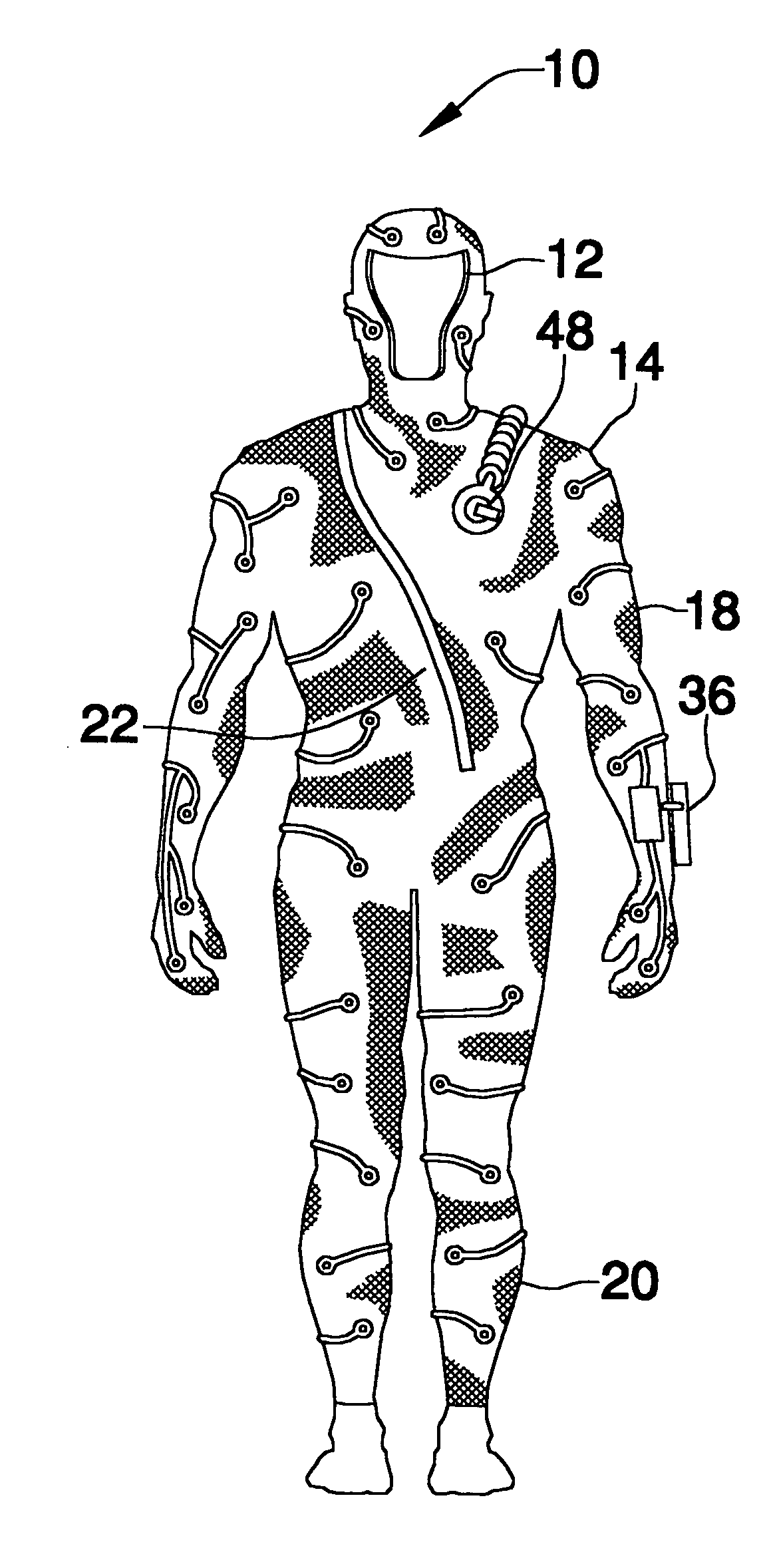
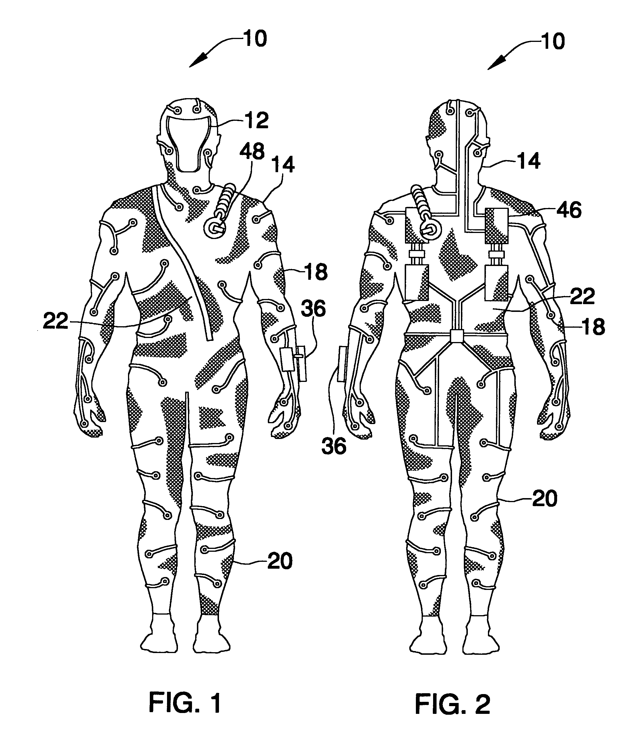
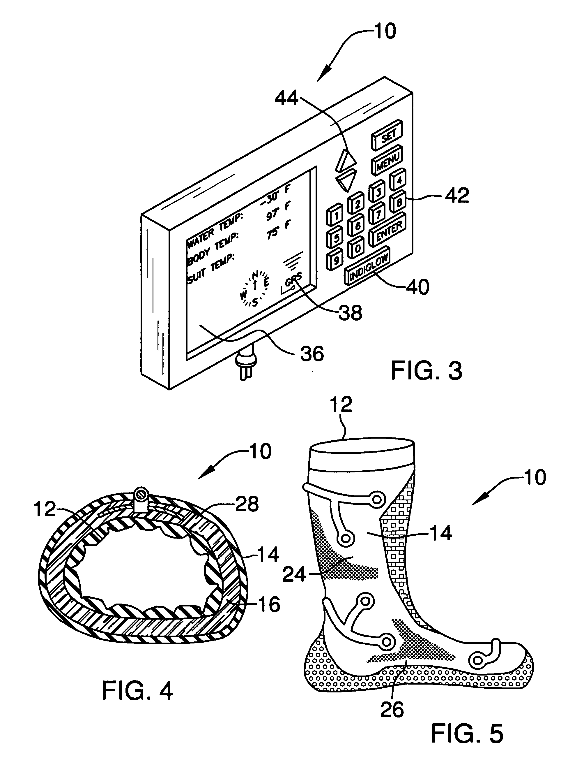
[0035]Referring now to the drawings, and particularly to FIGS. 1-6, a preferred embodiment of the heated underwater diving suit of the present invention is shown and generally designated by the reference numeral 10.

[0036]In FIG. 1, a new and improved heated underwater diving suit 10 of the present invention for self contained heated underwater diving suits having electronically controlled silicon gel heating elements is illustrated and will be described. More particularly, the heated underwater diving suit 10 has an inner liquid impervious yieldable sheet 12 (shown in FIG. 4). An outer liquid impervious yieldable sheet 14 is connected to the inner sheet 12. The inner sheet 12 and the outer sheet 14 forming a cavity 16 therebetween (shown in FIG. 4). The inner sheet 12 and the outer sheet 14 forms the structure having a set of arms 18, a set of legs 20 and a torso 22 portions. A silicon gel heating element 28 (shown in FIG. 4) is disposed within the cavity 16.

[0037]In FIG. 2, the hea...


PUM


Abstract

A self contained heated underwater diving suit having an inner liquid impervious yieldable sheet. An outer liquid impervious yieldable sheet is connected to the inner sheet. The inner sheet to the outer sheet forming a cavity therebetween. A silicon gel heating element is disposed within the cavity. A heating controller is electrically connected to the silicon gel heating element for controlling the heating of the silicon gel heating element.

Description

BACKGROUND OF THE INVENTION[0001]1. Field of the Invention[0002]The present embodiment of the invention relates to a heated underwater diving suit for use in connection with diving suits. The heated underwater diving suit has particular utility in connection with self contained heated underwater diving suits having electronically controlled silicon gel heating elements.[0003]2. Description of the Prior Art[0004]Heated underwater diving suits are desirable for diving in water that would cause a diver harm from hypothermia. A need was felt for a diving suit that had a self contained heating circuit and silicon gel heating elements.[0005]The use of diving suits is known in the prior art. For example, U.S. Pat. No. 5,960,469 to Nuckols et al. discloses a liquid-insulated garment for cold water diving supplements the inherent thermal protection of traditional suit insulations in conventional passive diving suits with bladders containing insulating liquids having substantially the same de...

Claims


Application Information

Patent Timeline
Patent Type & Authority Patents(United States)
IPC IPC(8): B63C11/28
CPCB63C11/28B63C11/04
Inventor SANDERS, WILLIAM M.
Owner SANDERS WILLIAM M
Why Eureka
Try Eureka