Battery terminal

a battery terminal and battery post technology, applied in the field of battery terminals, can solve the problems of low efficiency of operation, damage to the interposition portion b>171/b>, and insufficient fastening, so as to improve the efficiency of corrosion protection cover-attaching operation, enhance the reliability of battery terminal mounting on the battery post, and facilitate the passage of curved surfaces

Active Publication Date: 2007-12-11
YAZAKI CORP
View PDF2 Cites 4 Cited by
  • Summary
  • Abstract
  • Description
  • Claims
  • Application Information

AI Technical Summary

Benefits of technology

[0015]This invention has been made in view of the above circumstances, and an object of the invention is to provide a battery terminal which is capable of enhancing the reliability of mounting of this battery terminal on a battery post, and is capable of enhancing the efficiency of a corrosion-protective cover-attaching operation.
[0016]The above object has been achieved by a battery terminal of the first aspect of the present invention comprising a battery terminal body for mounting on a battery post, and a corrosion-protective cover disposed between the battery terminal body and a battery so as to prevent the corrosion of the battery terminal body, wherein the battery terminal body includes a pair of fastening portions each having a curved surface of a generally U-shape, an annular portion which has a battery post insertion hole, and extends from the pair of fastening portions, and a wire connection portion extending from the annular portion; the corrosion-protective cover is molded of a synthetic resin, and includes a base plate portion having a battery post insertion hole, a first hook portion formed at a rear end of the base plate portion so as to be engaged with the wire connection portion, and a second hook portion of a generally U-shape which is formed at a front end of the base plate portion, and has elasticity, and can be retainingly fitted on the curved surfaces, with the first hook portion engaged with the wire connection portion.

Problems solved by technology

As a result, when the mounting operation and the removing operation are repeated again and again, there is a fear that the mounting of the battery terminal on the battery post 103 is completed in such a manner that the fastening is not sufficiently effected because of interference of the inserted interposition portion 171.
There is another fear that the interposition portion 171 is damaged by the large fastening force acting thereon.
And besides, in the above conventional technique, the joined condition of the corrosion-protective cover 163 and battery terminal body 141 is unstable until the fastening bolt 159 is passed through the interposition portion 171, and therefore there is encountered a problem that the efficiency of the operation is low.
In addition, the fastening bolt 159 is withdrawn and inserted, for example, when exchanging the corrosion-protective cover 163, and therefore there is encountered a problem that the efficiency of the operation is low.

Method used


Image

  • Battery terminal
  • Battery terminal
  • Battery terminal

Examples


Embodiment Construction

[0044]The invention will now be described with reference to the drawings.

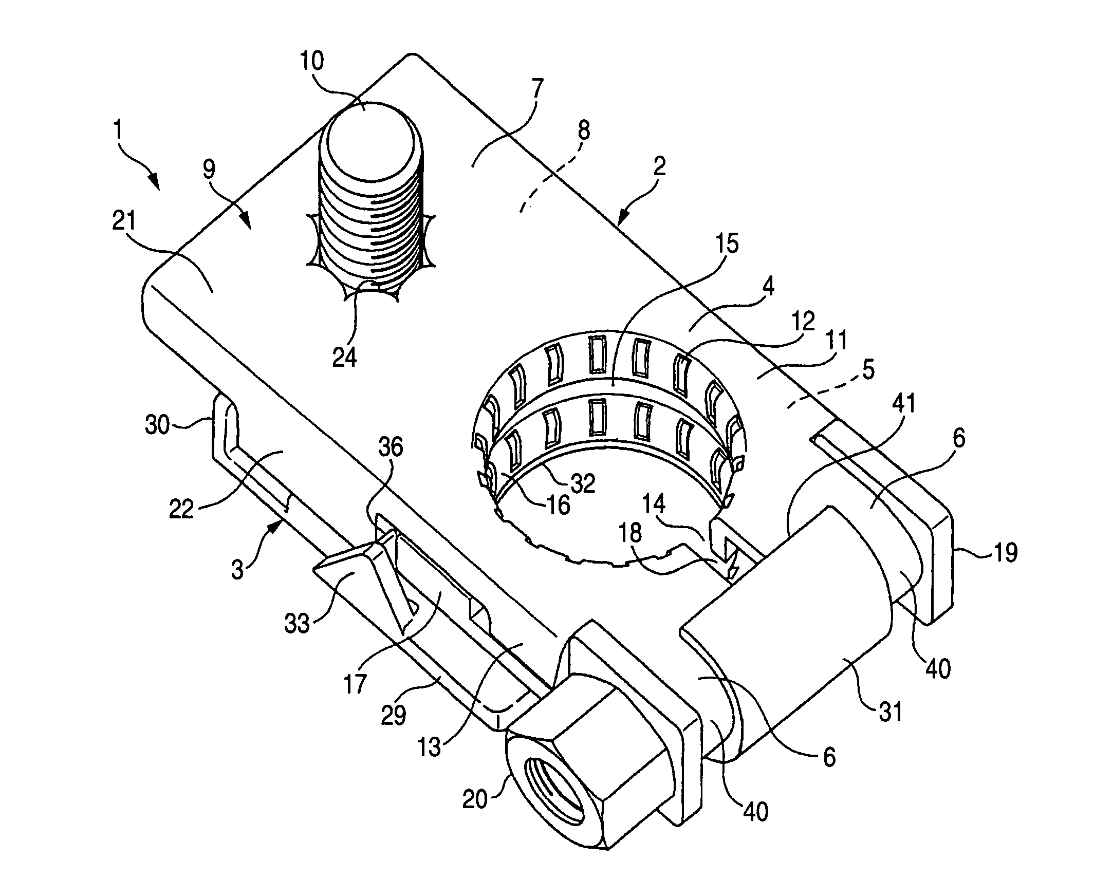
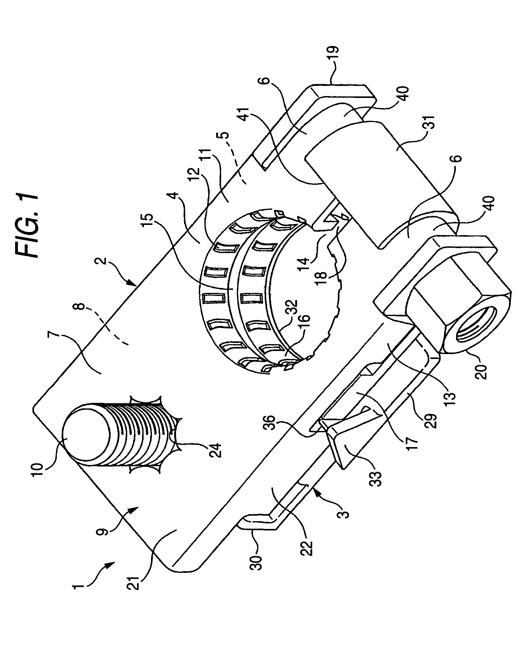
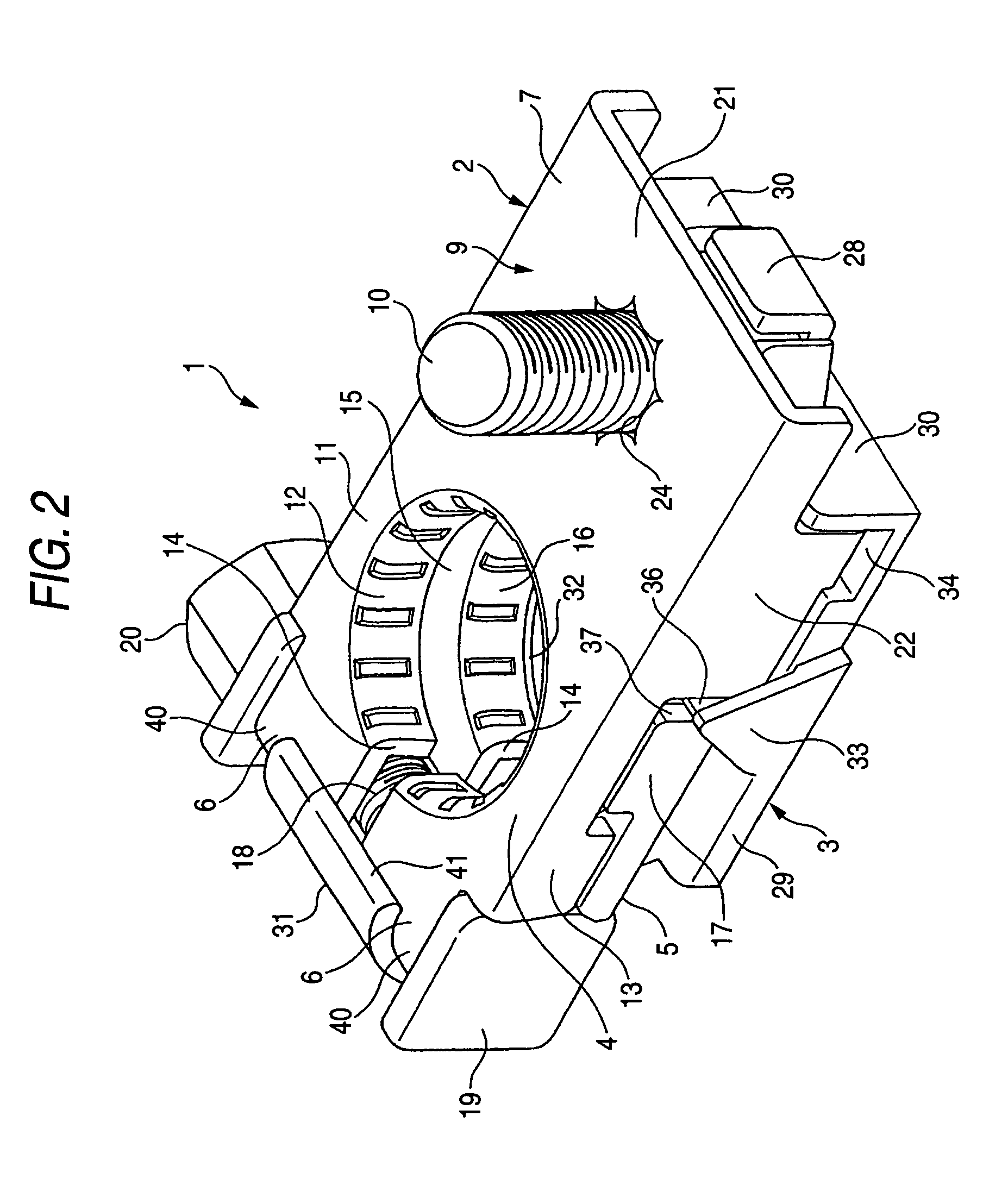
[0045]FIGS. 1 and 2 are perspective views showing one preferred embodiment of a battery terminal of the present invention. FIGS. 3 and 4 are perspective views of a battery terminal body, FIGS. 5 and 6 are perspective views of a corrosion-protective cover, FIG. 7 is a view explanatory of the difference between the centers, and FIGS. 8 to 10 are views explanatory of an attaching process.

[0046]In FIGS. 1 and 2, reference numeral 1 denotes the battery terminal for mounting around a known battery post 103 (see FIG. 11; The same shall apply hereinafter) having such a tapering peripheral surface that its distal end is smaller in diameter than its proximal end. The battery terminal 1 comprises the battery terminal body 2 for connection to a battery (not shown) mounted on a mobile body such as an automobile (although not particularly limited to such a mobile body), and the corrosion-protective cover 3 for preventing the...


PUM

PropertyMeasurementUnit
distance L2aaaaaaaaaa
radius R4aaaaaaaaaa
radius R4aaaaaaaaaa

Abstract

A corrosion-protective cover 3 is molded of a synthetic resin. The corrosion-protective cover 3 includes a base plate portion 29 having a battery post insertion hole, first hook portions 30 and 30 formed at a rear end of the base plate portion 29 so as to be engaged with a wire connection portion 9, and a second hook portion 31 of a generally U-shape which is formed at a front end of the base plate portion 29, and has elasticity, and can be retainingly fitted on curved surfaces 40 and 40 of fastening portions 6 and 6, with the first hook portions 30 and 30 engaged with the wire connection portion 9.

Description

BACKGROUND OF THE INVENTION[0001]1. Field of the Invention[0002]This invention relates to a battery terminal which comprises a battery terminal body for mounting on a battery post, and a corrosion-protective cover for preventing the corrosion of the battery terminal body.[0003]2. Related Art[0004]One known conventional battery terminal, including a battery terminal body and a corrosion-protective cover, is disclosed in Unexamined Japanese Patent Publication Hei. 10-12214.[0005]In FIG. 11, the battery terminal body 141 includes a pair of annular portions 145a and 145b arranged in an upward-downward direction. A battery post insertion hole 147 for the insertion of a battery post 103 therein is formed in each of the annular portions 145a and 145b. Each of the annular portions 145a and 145b is interrupted at a portion thereof in a circumferential direction to provide a fastening gap 149, and therefore each annular portion 145a, 145b is open at this interrupted portion.[0006]The upper an...

Claims


Application Information

Patent Timeline
Patent Type & Authority Patents(United States)
IPC IPC(8): H01M2/30H01M50/562H01R4/00H01R4/28
CPCH01M2/30Y02E60/10H01M50/543H01M50/562
Inventor FUJII, GAKUAKAMATSU, KUNIHIKO
Owner YAZAKI CORP
Why Eureka
Try Eureka