
Apparatus for irradiating a target volume

a target volume and apparatus technology, applied in the field of apparatus for irradiating a target volume, can solve the problems of discrepancy between actual and required dose, and no certainty given that the actual dose applied is equal to the required dose map

Inactive Publication Date: 2007-12-11
ION BEAM APPL
View PDF11 Cites 148 Cited by
  • Summary
  • Abstract
  • Description
  • Claims
  • Application Information

AI Technical Summary

Problems solved by technology

In the above scheme, however, no certainty is given that the actual dose applied is equal to the required dose map.
Many sources of noise, drift and errors may result in a discrepancy between actual and required dose.

Method used


Image

  • Apparatus for irradiating a target volume
  • Apparatus for irradiating a target volume
  • Apparatus for irradiating a target volume

Examples


Embodiment Construction

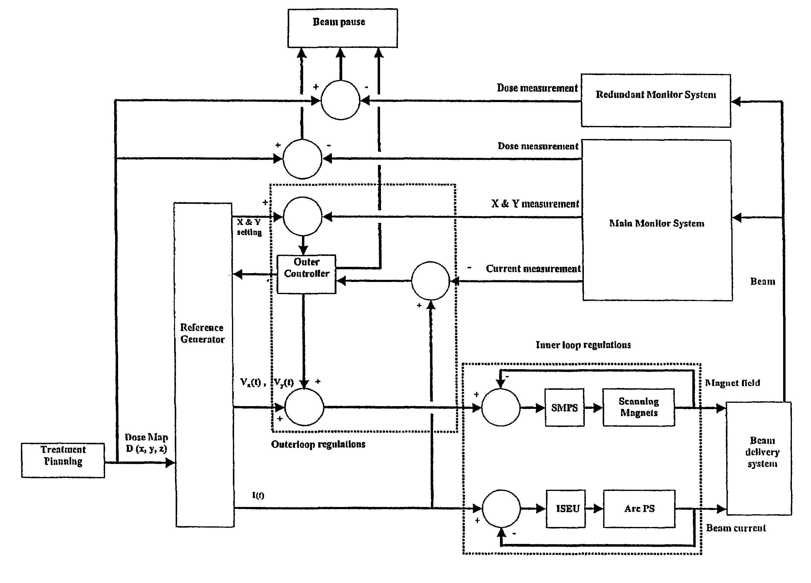
[0043]A first embodiment of the present invention is illustrated on FIG. 3.

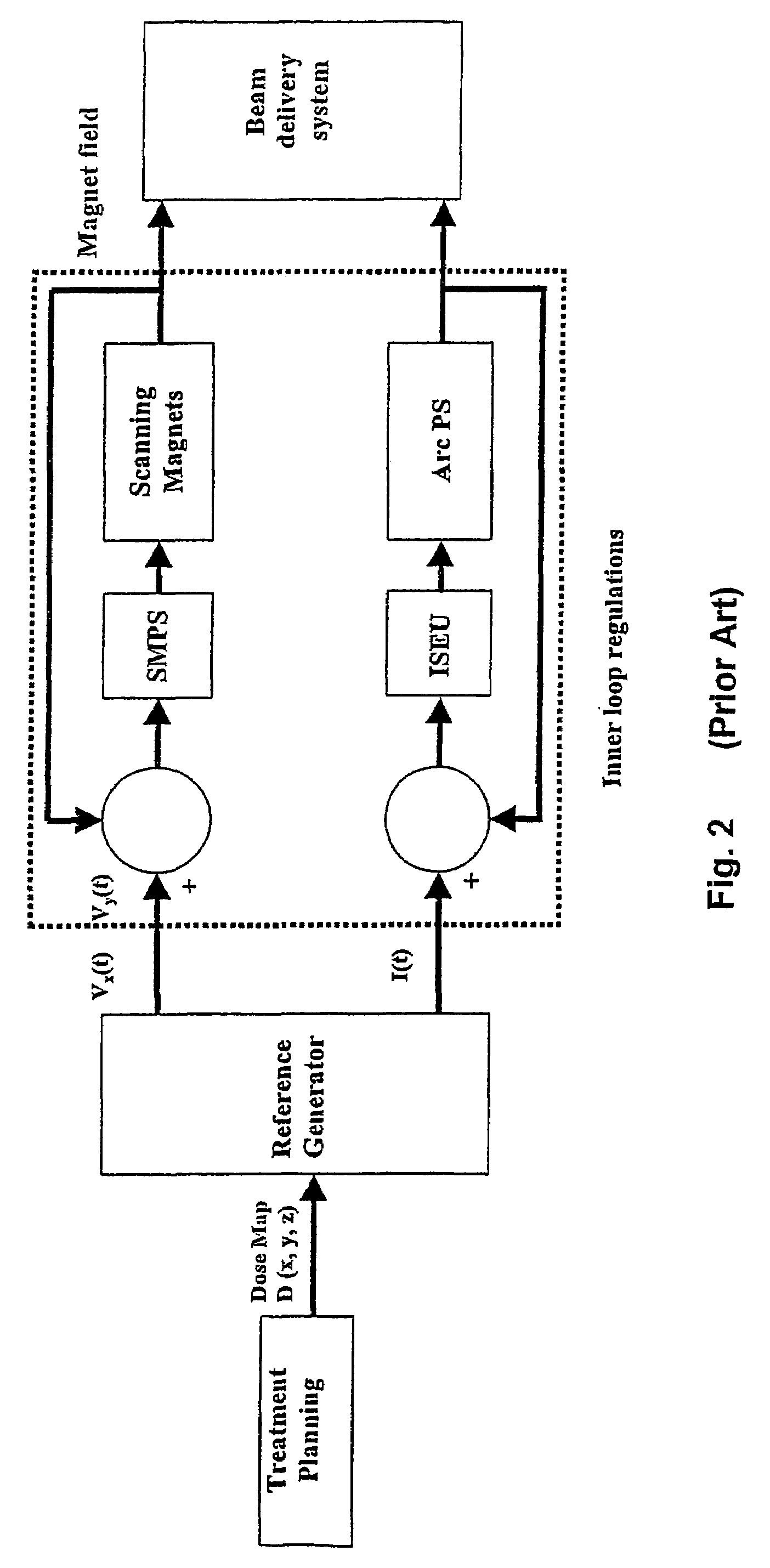
[0044]Using the treatment planning system, the therapist generates a dose map D(x,y,z) representing the dose for each point x,y,z in the target. The reference generator computes the trajectories, comprising the required speed vx(t), vy(t),the required beam current I(t), and, in addition, the required position x(t), y(t). The speed data are sent to a scanning magnet power supply (SMPS). The coil of a scanning magnet being, in first approximation, a pure inductance, the current through the coil is proportional to the time integral of the applied voltage. The displacement of the beam is proportional to the field, and hence to the current. Therefore, by applying to the coils of the scanning magnets a voltage proportional to the required speed vx(t) or vy(t), one obtains the required beam spot speed.

[0045]According to the invention, an outer control loop for controlling the dose comprises the following elements: a...


PUM


Abstract

An irradiation apparatus for irradiating by scanning a target volume according to a predetermined dose profile with a scanning beam of charged particles forming an irradiation spot on said target volume, said apparatus comprising:a beam generating device,a reference generator for computing, from said predetermined dose profile, through a dynamic inverse control strategy, the time evolution of commanded variables, these variables being the beam current I(t), the spot position settings x(t),y(t) and the scanning speed settings vx(t), vy(t),a monitor device having means for detecting at each time (t), the actual spot position as a measured position defined by the values xm(t),ym(t) on the target volume,characterised in that said irradiation apparatus further comprises means for determining the differences ex(t), ey(t) between the measured values xm(t), ym(t) and the spot position settings x(t) and y(t), and means for applying a correction to the scanning speed settings vx(t) and vy(t) depending on said differences ex(t), ey(t). The present invention is also related to a monitor for determining beam position in real-time.

Description

FIELD OF THE INVENTION[0001]The present invention is related to an apparatus for irradiating a target volume with a beam of charged particles such as protons or heavy ions and to a method for implementing said apparatus.[0002]The present invention is also related to an apparatus for monitoring said beam.[0003]A possible application of such apparatus is for the treatment of tumors in patients.STATE OF THE ART[0004]Many types of irradiation systems are used for the treatment of tumors in patients. It is important to precisely deliver the required dose to the tumor region, and as little dose as possible to the environing healthy tissues. It has been known to use X-rays or gamma rays for this purpose. High-energy electrons have also been used. However, heavier charged particles have the property that they deposit energy in matter according to the so-called “Bragg-peak”, i.e. a dose-depth curve having a plateau, a peak, and a sharp fall-off beyond the peak. The height of the peak corresp...

Claims


Application Information

Patent Timeline
Patent Type & Authority Patents(United States)
IPC IPC(8): H01J33/02A61N5/10G21K1/087H01J47/06
CPCA61N5/10A61N5/1043G21K1/087A61N2005/1087A61N5/1048
Inventor BRUSASCO, CATERINAMARCHAND, BRUNODE LE HOYE, JEAN-FRANCOISPRIEELS, DAMIEN
Owner ION BEAM APPL
Learn More