
Dosimetry device for charged particle radiation

一种带电粒子束、剂量分布的技术,应用在测量装置、剂量计、辐射的测量等方向,能够解决成本提高、阳极电极数量不能太大、基板块数增加等问题,达到低成本的效果

Active Publication Date: 2008-03-12
MITSUBISHI ELECTRIC CORP
View PDF0 Cites 9 Cited by
  • Summary
  • Abstract
  • Description
  • Claims
  • Application Information

AI Technical Summary

Problems solved by technology

Therefore, cables and connectors must be used to connect the frame with each anode electrode and the substrate on which the signal processing circuit is installed. If the size of the connector and the number of practical cables are considered, the number of anode electrodes should not be too large. Improved resolution of dose distribution
In addition, since the total number of substrates of the frame on which each anode electrode is arranged and the substrate on which the signal processing circuit is mounted increases, the cost increases.

Method used


Image

  • Dosimetry device for charged particle radiation
  • Dosimetry device for charged particle radiation
  • Dosimetry device for charged particle radiation

Examples


Embodiment Construction

[0043] Several embodiments of the present invention will be described below with reference to the drawings.

[0044] Embodiment 1

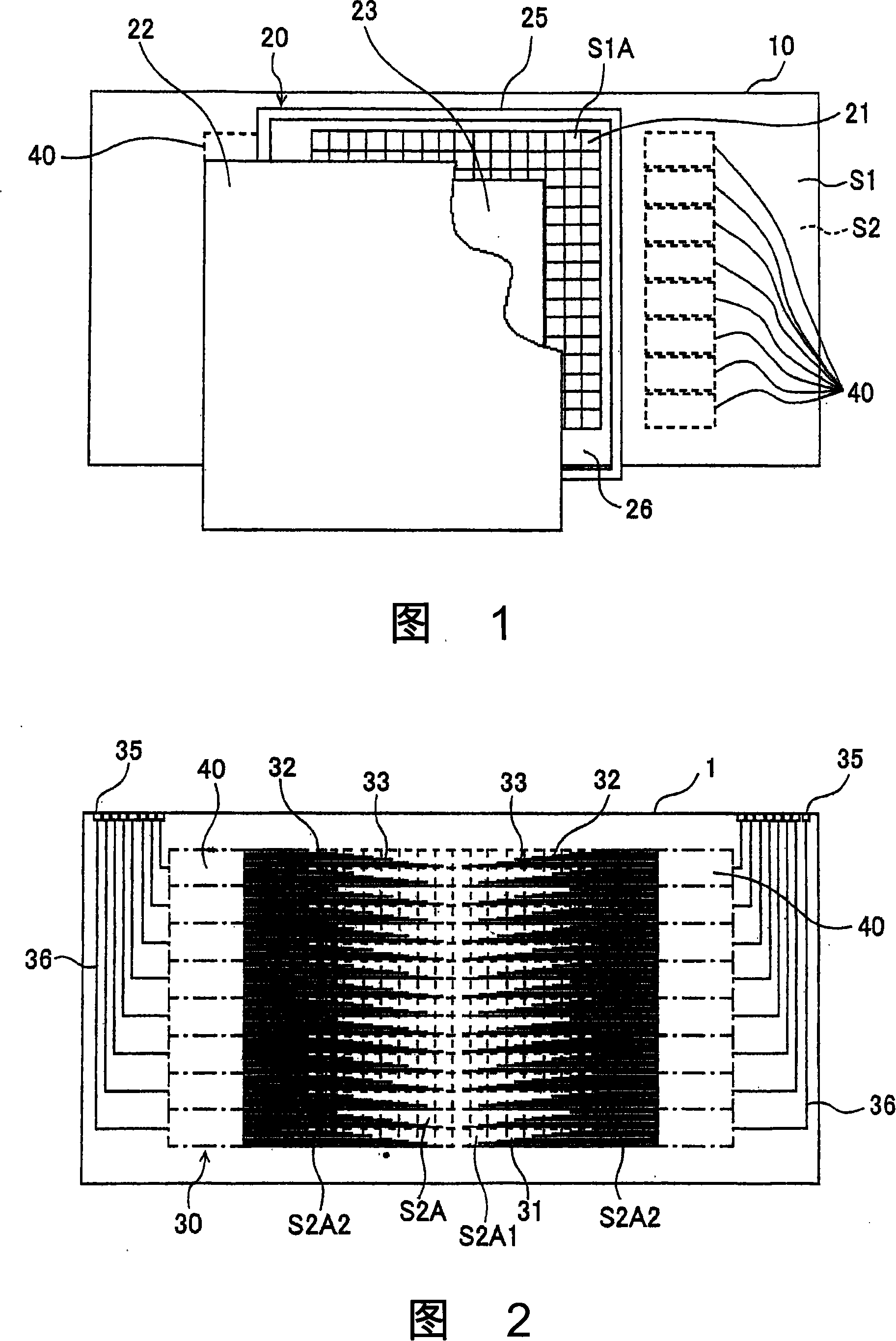
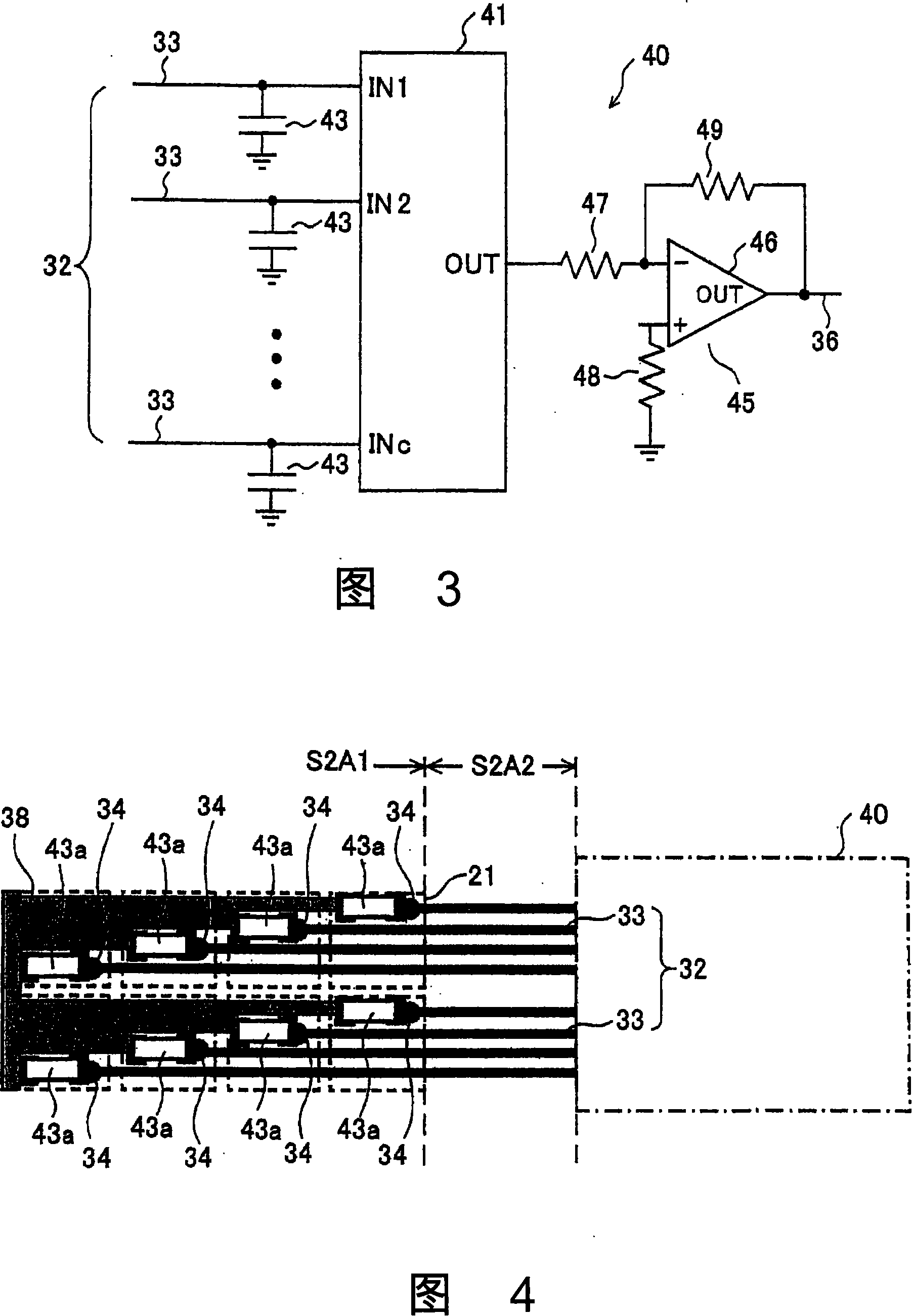
[0045] Fig. 1 is a configuration diagram showing Embodiment 1 of a charged particle beam dose distribution measuring device according to the present invention, Fig. 2 is a rear view of a printed circuit board in Embodiment 1, and Fig. 3 is a signal processing circuit in Embodiment 1 The circuit diagram of 1 signal processing module.

[0046] Referring first to FIG. 1 . As shown in FIG. 1 , the charged particle beam distribution measuring device according to Embodiment 1 is constituted by using a single printed circuit board (PCB) 10 . This printed circuit board 10 has a pair of main surfaces S1 and S2 facing each other. The main surface S1 is, for example, the front side of the printed circuit board 10 , and the main surface S2 is the reverse side thereof. The printed circuit board 10 is a double-sided printed circuit board, and circuit elemen...


PUM


Abstract

A dosimetry device for charged particle radiation that can be exclusive of cables and connectors between substrates is provided. A plurality of first electrodes are formed on one surface of a printed circuit board, a second electrode substrate having a second electrode opposing each of the plurality of first electrodes through an ionized space is provided, and a signal processing circuit is provided on the other surface opposing the surface of the printed circuit board. The signal processing circuit includes at least one amplifying circuit, a plurality of integrating capacitors corresponding to the amplifying circuit for integrating charge at each corresponding one of the first electrodes, and at least one selector switch that switchably connects each of the integrating capacitors to the amplifying circuit. The printed circuit board may be a multi-layer printed circuit board.

Description

technical field [0001] The present invention relates to a dose distribution measuring device for measuring the dose distribution of a charged particle beam. Background technique [0002] A conventional charged particle beam dose distribution measuring device includes, for example, the device disclosed in Non-Patent Document 1 below. [0003] [Non-Patent Document 1] On pages 674-686 of the "Physical Research A519 of Nuclear Instruments and Methods" (nuclear instruments and methods in physics research A 519) issued in 2004, an article called "Intensive Particle Therapy" was published. A pixel chamber to monitor the beam performances in hadrontherapy" paper. [0004] The charged particle beam dose distribution measuring device disclosed in this Non-Patent Document 1 has: an ionization chamber composed of a high-voltage electrode (cathode), a spacer frame, and a plurality of frames in which the anode electrodes are arranged in a matrix; The signal processing circuit of the sig...

Claims


Application Information

Patent Timeline
Patent Type & Authority Applications(China)
IPC IPC(8): G01T1/29
CPCG01T1/02A61N5/1075A61N2005/1087
Inventor 山本雄一
Owner MITSUBISHI ELECTRIC CORP
Learn More