Safety switches

a safety switch and switch technology, applied in the field of safety switches, can solve the problems of increased product cost and inability to set the switch member, and achieve the effect of reducing manufacturing cos

Inactive Publication Date: 2007-12-11
YU TSUNG MOU
View PDF39 Cites 13 Cited by
  • Summary
  • Abstract
  • Description
  • Claims
  • Application Information

AI Technical Summary

Benefits of technology

[0008]The main object of the present invention is to provide a safety switch that provides a push rod extending from the underside of the switch member and the spring member connected with the contact portion includes a through hole which allows the push rod to extend therethrough so as not to stop the upward movement of the spring member when overloaded.
[0009]Another object of the present invention is to provide a safety switch wherein the two ends of the switch member are in contact with the two ends of the contact plate such that the contact plate is moved precisely.
[0010]Yet another object of the present invention is to provide a safety switch that includes less number of parts so as to have lower manufacturing cost.

Problems solved by technology

There are too many parts involved in the safety switches and a longer period of time is required when assembling the switches, so this increases the cost of the products.
Because of the inaccuracy of the deformation of the bi-metallic plate, the switch member cannot be set at “OFF” position after the bimetallic plate is deformed to cut off the circuit.

Method used


Image

  • Safety switches
  • Safety switches
  • Safety switches

Examples


Embodiment Construction

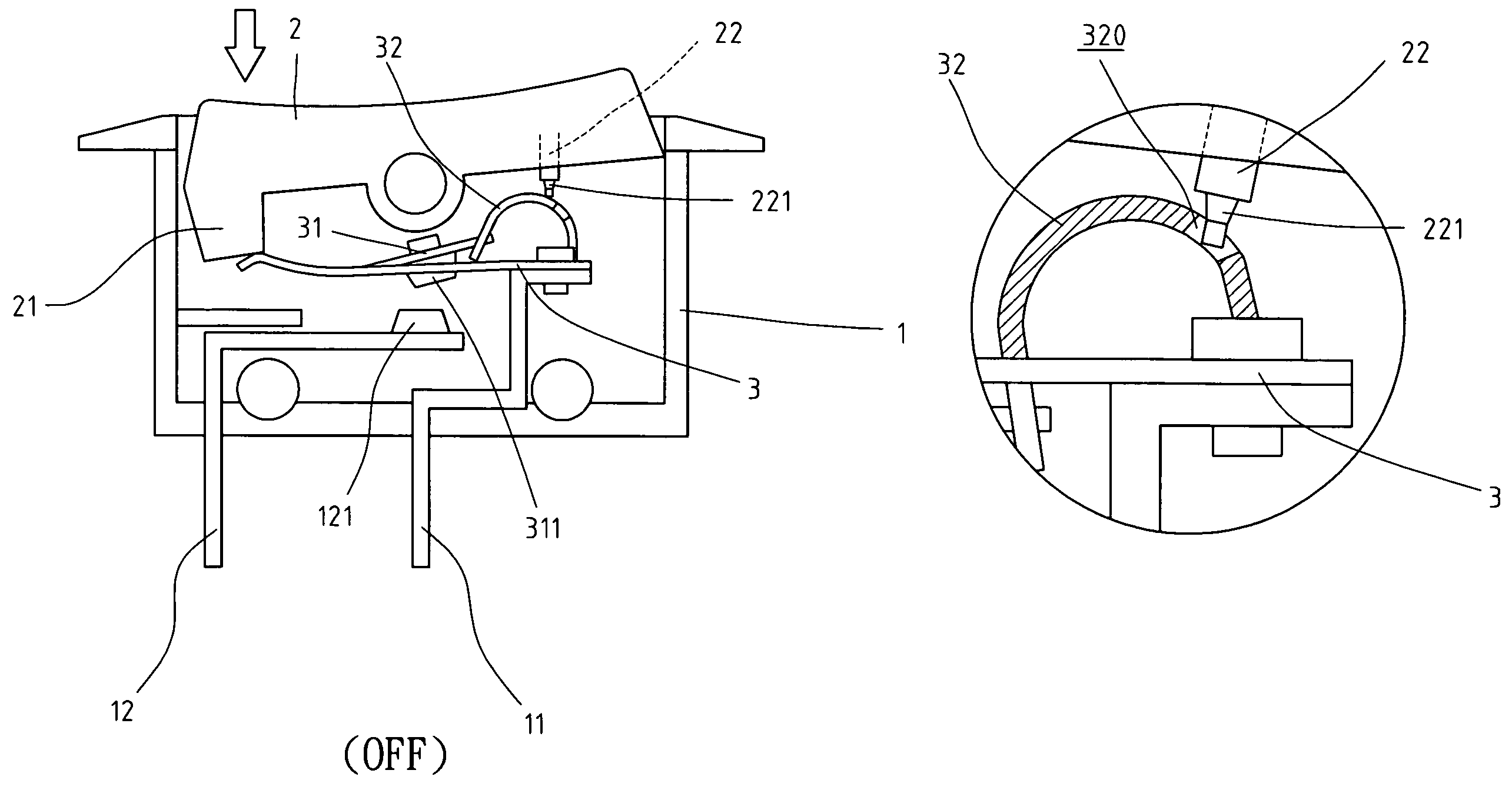
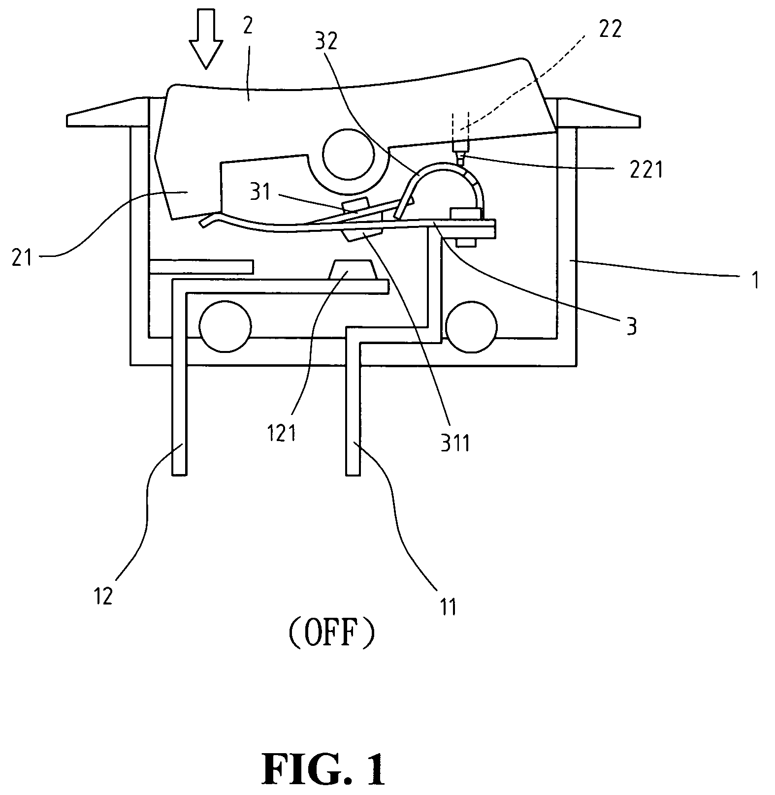
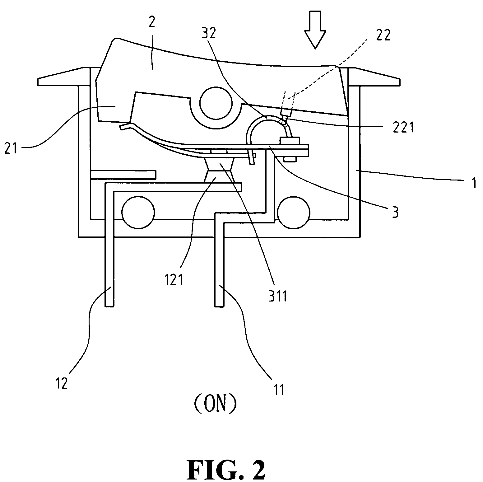
[0018]Referring to the drawings and in particular to FIGS. 1, 2 and 6, a safety switch in accordance with the present invention comprises a body 1 with a top opening and a switch member 2 is pivotably engaged with the top opening of the body 1 such that the switch member 2 is pivoted about a pin at a middle portion thereof. An extension 21 extends from a first end of an underside of the switch member 2 and a push rod 22 extends from a second end of the underside of the switch member 2. A protrusion 221 extends axially from a distal end of the push rod 22. The protrusion 221 is a cylindrical and tapered protrusion and a distal end of the protrusion is rounded. The diameter of the protrusion 221 is smaller than that of the push rod 22. A first terminal 11 and a second terminal 12 extend through a bottom of the body 1.

[0019]A contact plate 3, which is a curved flexible bi-metallic plate, has a first end fixed to the first terminal 11 and a second end of the contact plate 3 is a free en...


PUM


Abstract

A switch includes a switch member and an extension and a push rod respectively extended from two ends of an underside of the switch member. A bi-metallic contact plate has a first end fixed to one of two terminals and a contact portion splits from the contact plate. A first contact point is connected to an underside of the contact portion and a second contact point is connected to the other terminal. A free end of the contact portion is connected with a free first end of a spring member and a second end of the spring member is connected to the contact plate. When overload, the contact portion and the spring member move upward to cut off the circuit while the push rod extends through a through hole defined in the spring member.

Description

BACKGROUND OF THE INVENTION[0001]1. Field of the Invention[0002]The present invention relates to a safety switch that ensures the bi-metallic plate to be deformed as desired when overloaded.[0003]2. The Prior Arts[0004]A conventional switch device, especially for those switches using bi-metallic plate to prevent from being burn when an overload happens, generally includes a bi-metallic plate which is deformed when overloaded so as to separate the two contact points respectively located on the bimetallic plate and one of the two terminals. Some inherent shortcomings for these conventional safety switches are experienced. There are too many parts involved in the safety switches and a longer period of time is required when assembling the switches, so this increases the cost of the products. The parts might be arranged inaccurately and affect the deformation of the bi-metallic plate. Once the bimetallic plate is deformed to cut off the circuit, because of the improper arrangement of the...

Claims


Application Information

Patent Timeline
Patent Type & Authority Patents(United States)
IPC IPC(8): H01H37/70H01H37/18H01H37/52
CPCH01H73/26
Inventor YU, TSUNG MOU
Owner YU TSUNG MOU
Why Eureka
Try Eureka