Heat dissipation mechanism for electronic apparatus

a technology of electronic equipment and heat dissipation mechanism, which is applied in the direction of electrical equipment casings/cabinets/drawers, power cables, insulated conductors, etc., can solve the problems of reducing the life of electronic devices, generating huge amounts of heat, and affecting the use of electronic devices, so as to prevent the burning of human skin and dissipate heat more effectively

Active Publication Date: 2007-12-11
TAICHI HLDG
View PDF17 Cites 33 Cited by
  • Summary
  • Abstract
  • Description
  • Claims
  • Application Information

AI Technical Summary

Benefits of technology

[0008]Besides, an another aspect of the invention is to provide a heat dissipation mechanism for small, portable electronic apparatus for dissipating heat more effectively. In order to prevent the burning of human skin, the design for heat dissipating regions (specially the heat dissipating openings) are specified to prevent the human skin to sink into the openings, touch the inner metal pieces and get burnt.

Problems solved by technology

. . etc., generate huge amounts of heat because of the power consumption caused by impedance when they are transmitting or processing data.
If the generated heat is not properly dissipated from the devices, it may influence the process efficiency of the electronic apparatus, reduce their usage life span, furthermore the electronic devices will be broken.
Therefore, if an electronic apparatus consists of foregoing heat generated devices, heat dissipation problems must be considered to ensure the process efficiency and the usage life span thereof.
However, the generated heat of the electronic device is going to stock in the housing and does harm to the other electronic devices if without any heat dissipation mechanism.
However, an electric fan consumes power and occupies space, therefore it may not suitable to some devices (i.e., a flash drive, a mini-mp3 player, or a wireless network card).
But if only the heat dissipating openings are applied, the dissipating efficiency is too bad and unacceptable.

Method used


Image

  • Heat dissipation mechanism for electronic apparatus
  • Heat dissipation mechanism for electronic apparatus
  • Heat dissipation mechanism for electronic apparatus

Examples


Embodiment Construction

[0022]The present invention will now be described in detail with reference to the drawings, which are provided as illustrative examples of the invention so as to enable those skilled in the art to practice the invention. Moreover, where certain elements of the present invention can be partially or fully implemented using known components, only those portions of such known components that are necessary for an understanding of the present invention will be described, and detailed descriptions of other portions of such known components will be omitted so as not to obscure the invention.

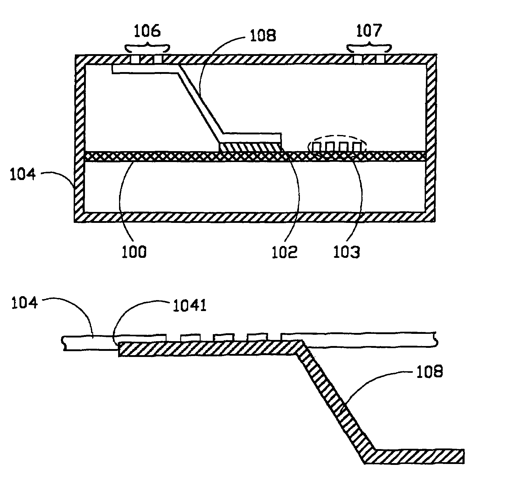
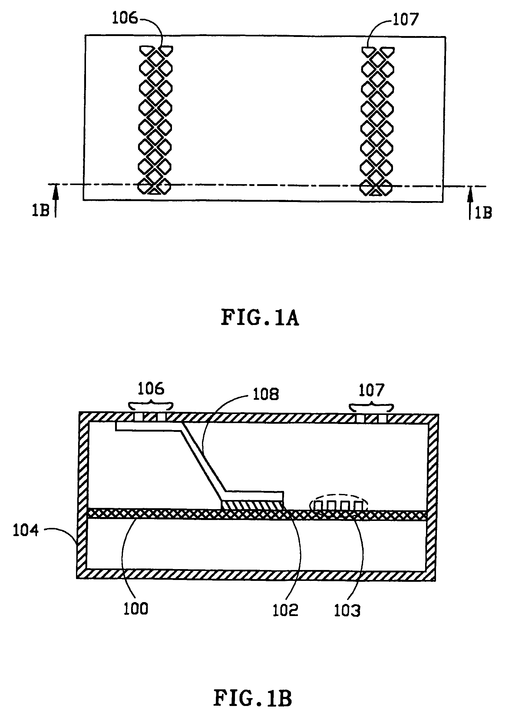
[0023]FIG. 1A and FIG. 1B illustrate the housing for a heat dissipation mechanism with the preferred embodiment of the invention and its cutaway view from 1B direction respectively. Substrate 100, on which fastened at least a thermal device 102 and the other devices 103. Thermal device 102 is the major heat source of an electronic apparatus, and the material for the substrate 100 is a printed circuit boa...


PUM


Abstract

This disclosure presents a heat dissipation mechanism, which conducts generated heat of a thermal device to the housing of an electronic apparatus by a metal piece fastened between the thermal device and electronic apparatus, and then dissipates heat into the air through multiple holes opened over an apparatus shell. Besides, the presented mechanism is also suitable to mini-size, portable electronic apparatus to solve the thermal dissipation technique thereof.

Description

BACKGROUND OF THE INVENTION[0001]1. Field of the Invention[0002]The presented invention relates to a heat dissipation mechanism, which conducts generated heat of a thermal device for housing of electronic apparatus by a metal piece.[0003]2. Description of the Prior Art[0004]Some electronic devices, such as a CPU, north bridge, or VGA . . . etc., generate huge amounts of heat because of the power consumption caused by impedance when they are transmitting or processing data. If the generated heat is not properly dissipated from the devices, it may influence the process efficiency of the electronic apparatus, reduce their usage life span, furthermore the electronic devices will be broken. Therefore, if an electronic apparatus consists of foregoing heat generated devices, heat dissipation problems must be considered to ensure the process efficiency and the usage life span thereof. Nowadays lots of heat dissipation mechanisms are proposed, the apparatus designers may achieve the goals fo...

Claims


Application Information

Patent Timeline
Patent Type & Authority Patents(United States)
IPC IPC(8): H05K7/20H01L23/433H05K5/00
CPCH01L23/433H05K7/20445H01L2924/3011H01L2924/0002H01L2924/00
Inventor WU, CHUNG-JU
Owner TAICHI HLDG
Why Eureka
Try Eureka