Memory card with raised portion

a memory card and raised portion technology, applied in the testing/measurement of individual semiconductor devices, semiconductor/solid-state devices, instruments, etc., can solve the problems of limiting the size of memory cards manufactured, the top and bottom lids are relatively expensive to manufactur

Active Publication Date: 2007-12-11
SANDISK TECH LLC
View PDF104 Cites 53 Cited by
  • Summary
  • Abstract
  • Description
  • Claims
  • Application Information

AI Technical Summary

Benefits of technology

[0061]The foregoing detailed description of the invention has been presented for purposes of illustration and description. It is not intended to be exhaustive or to limit the invention to the precise form disclosed. Many modifications and variations are possible in light of the above teaching. The described embodiments were chosen in order to best explain the principles of the invention and its practical application to thereby enable others skilled in the art to best utilize the invention in various embodiments and with various modifications as are suited to the particular use contemplated. It is intended that the scope of the invention be defined by the claims appended hereto.

Problems solved by technology

First, the test pins that are cut off use real estate on the circuit board.
Second, if the memory card fails in the field, there are no test pins to test the device in order to determine why the memory card failed.
There will be a small air gap between the bottom lid and the bottom of the circuit board While this design works well, the top and bottom lids are relatively expensive to manufacture.
Additionally, the lids are relatively bulky which limits how small the memory cards can be manufactured.
Similar issues exist with other types of peripheral cards, such as peripheral cards that implement wireless communication devices, GPS devices, cellular devices, network interfaces, modems, disk storage systems, and other devices.

Method used


Image

  • Memory card with raised portion
  • Memory card with raised portion
  • Memory card with raised portion

Examples


Embodiment Construction

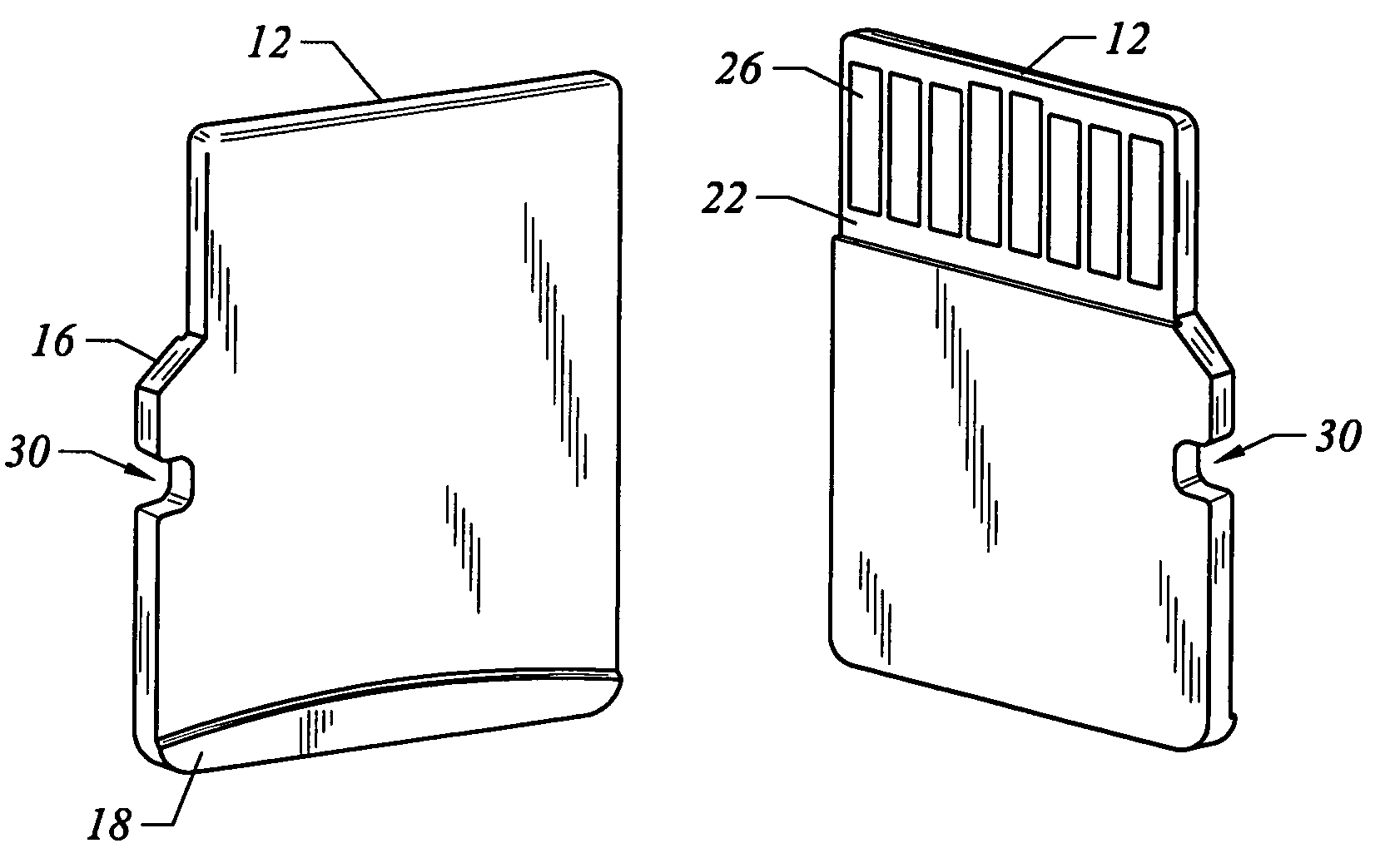
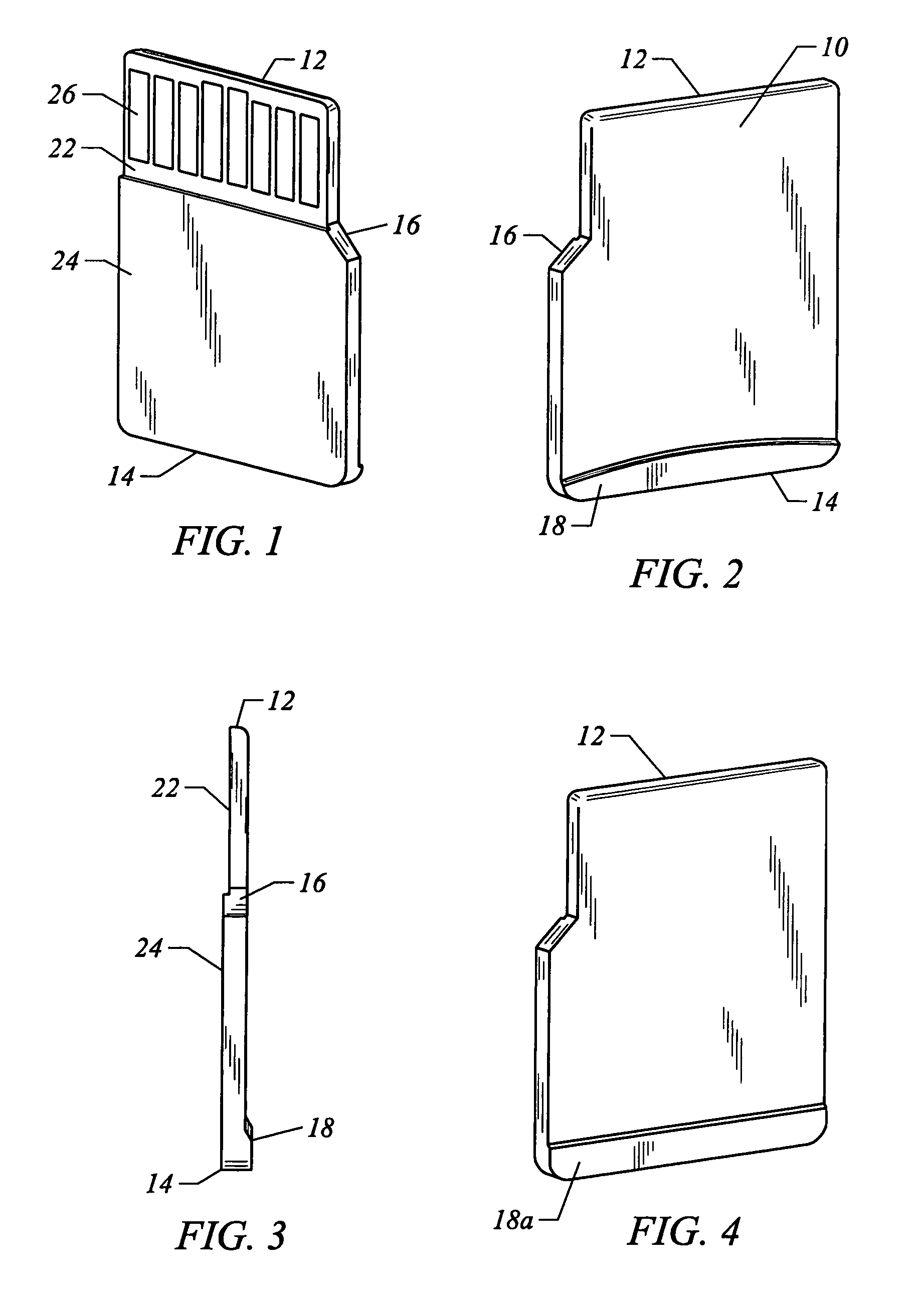
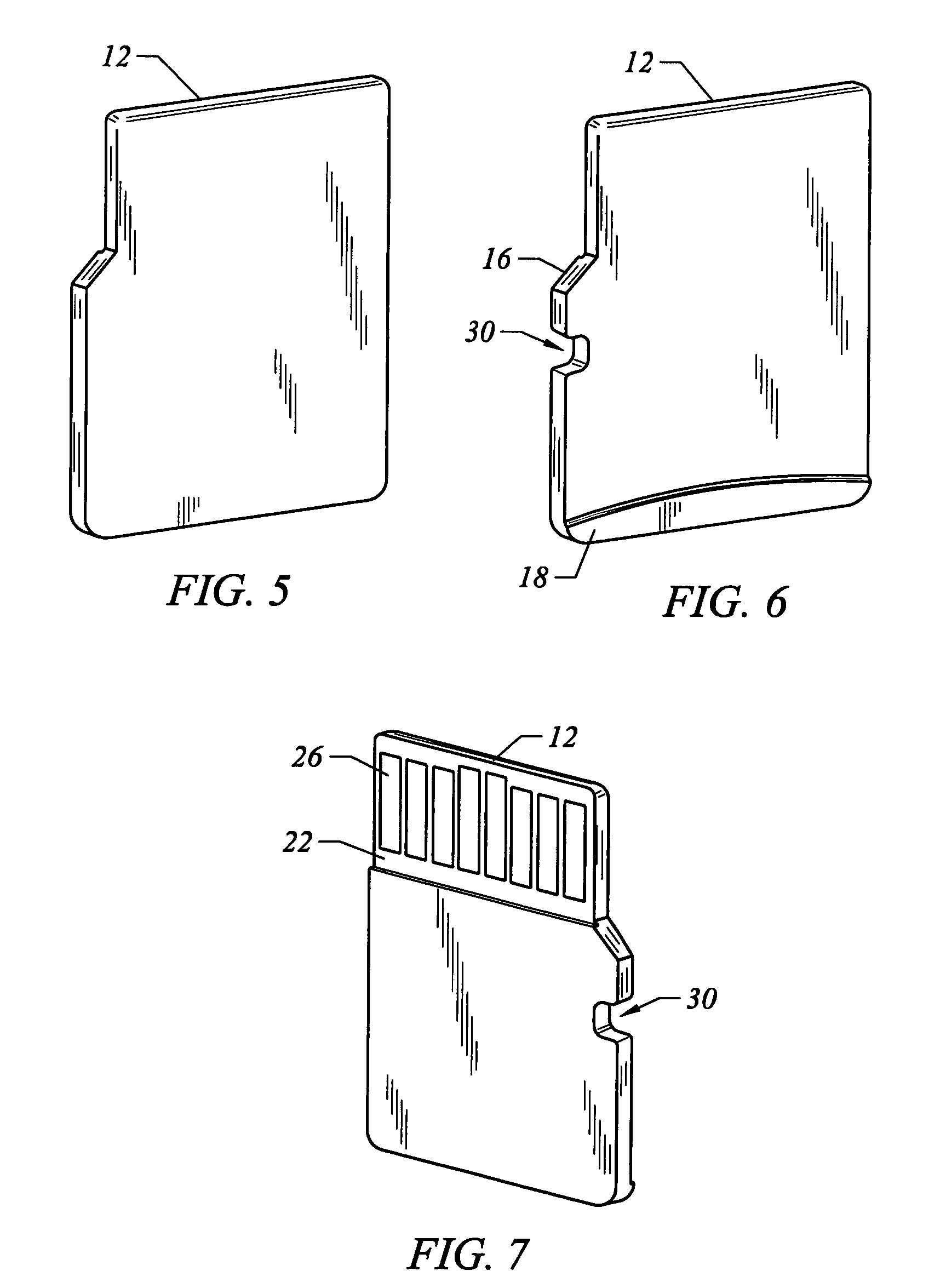
[0039]FIGS. 1-10 depict various embodiments of a memory card. For example, FIG. 1 is a perspective view of the bottom of a memory card according to a first embodiment of the present invention. FIG. 2 is a perspective view of the top of the memory card according to the first embodiment of the present invention. FIG. 3 is a side view of the memory card according to the first embodiment of the present invention. The memory card of FIGS. 1-3 includes a top surface 10, a bottom surface, a front surface 12, a back surface 14 and two side surfaces. One of the side surfaces has an angle portion 16. Top surface 10 has a raised portion 18 adjacent to back surface 14. Raised portion 18 allows the memory card to be more easily grabbed by a human hand (or mechanical device) and also provides additional room to store passive devices such as capacitors and / or resistors. Note that raised portion 18 of FIG. 1 has a curved profile. The bottom surface includes a first portion 22 and a second portion 2...


PUM

PropertyMeasurementUnit
angleaaaaaaaaaa
thicknessaaaaaaaaaa
thicknessaaaaaaaaaa

Abstract

A peripheral card includes a circuit board, various circuit elements on the circuit board, a set of user terminals, a set of test terminals, and an enclosure that covers a portion of the circuit board and the circuit elements. The enclosure does not cover the user terminals and test terminals. After the peripheral card is tested, the test terminals are covered with a conformal contact coating in order to prevent access to the test terminals.

Description

[0001]This application is a continuation application of U.S. patent application Ser. No. 10 / 621,882, entitled“Peripheral Card with Hidden Test Pins,” filed Jul. 17, 2003, incorporated herein by reference in its entirety.CROSS-REFERENCE TO RELATED APPLICATIONS[0002]This Application is related to U.S. patent application Ser. No. 10 / 602,373, “Method For Efficiently Producing Removable Peripheral Cards,” filed Jun. 23, 2003, Hem P. Takiar, which is incorporated herein by reference in its entirety.BACKGROUND OF THE INVENTION[0003]1. Field of the Invention[0004]The present invention is directed to technology for peripheral cards.[0005]2. Description of the Related Art[0006]Memory cards are relatively small removable cards that provide data storage. In most cases, but not required in all cases, the memory card is integrated circuit based. These memory cards plug into or are received by ports or connectors on electronic devices, including computing devices, cameras, mobile telephones, PDAs ...

Claims


Application Information

Patent Timeline
Patent Type & Authority Patents(United States)
IPC IPC(8): H05K1/14G06K19/077H05K1/02H05K3/28
CPCG06K19/077H05K1/0268G06K19/07732Y10T29/4913H01L2224/32145H01L2224/48091H01L2224/48227H01L2924/01004H01L2924/1815H01L2924/19041H05K3/284Y10T29/49179Y10T29/49169Y10T29/49004H01L2224/73265H01L2224/32225H01L2924/00014H01L2924/00012H01L24/73H01L2924/14H01L2924/00G06K19/00G06K19/07
Inventor TAKIAR, HEM P.
Owner SANDISK TECH LLC
Why Eureka
Try Eureka