Method and system for cooling electrical components downhole

a technology for electrical components and cooling systems, applied in the direction of borehole/well accessories, lighting and heating apparatus, machine operation modes, etc., to achieve the effect of effectively cooling electrical components

Inactive Publication Date: 2007-12-18
SCHLUMBERGER TECH CORP
View PDF10 Cites 21 Cited by
  • Summary
  • Abstract
  • Description
  • Claims
  • Application Information

AI Technical Summary

Benefits of technology

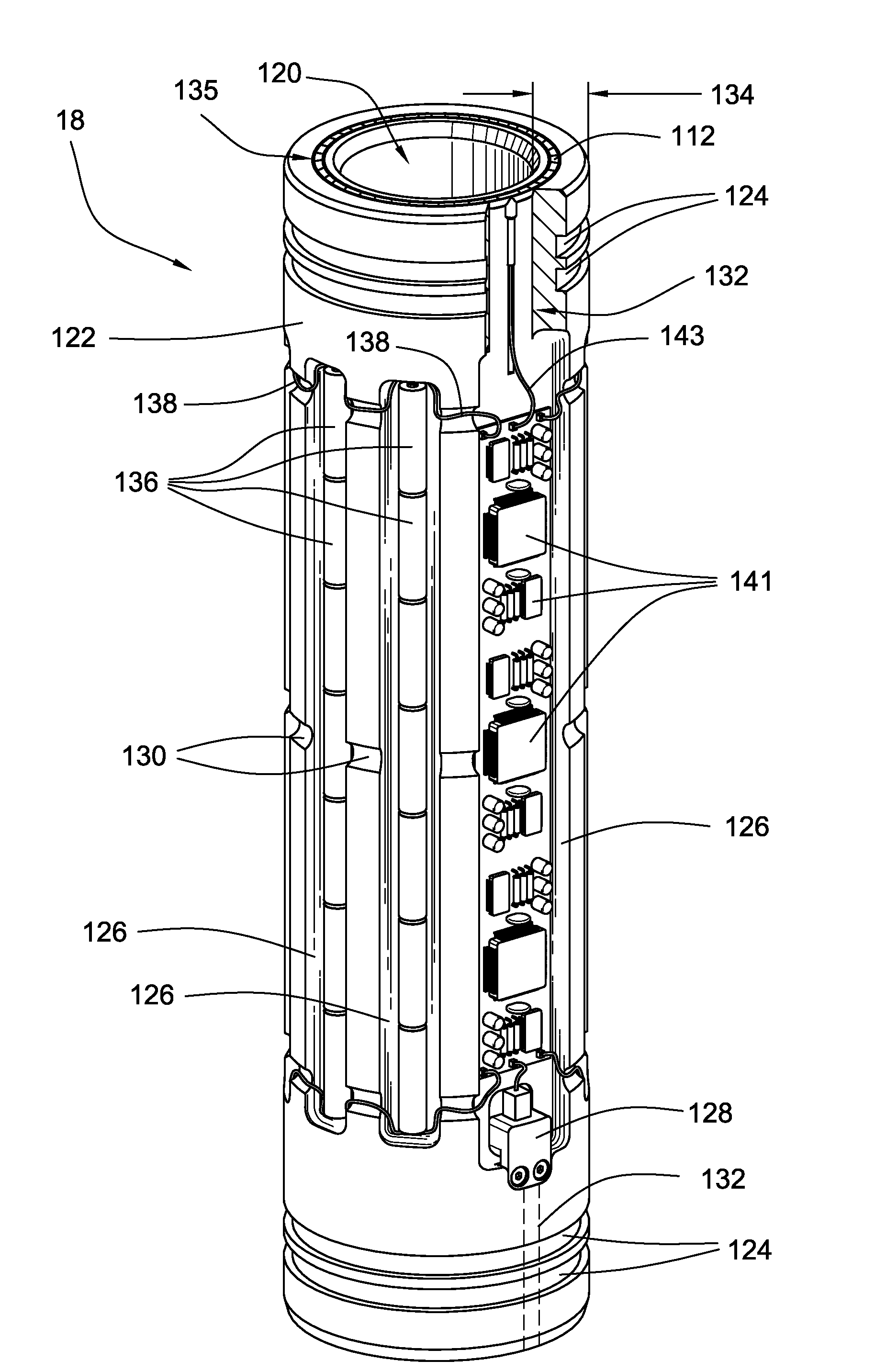
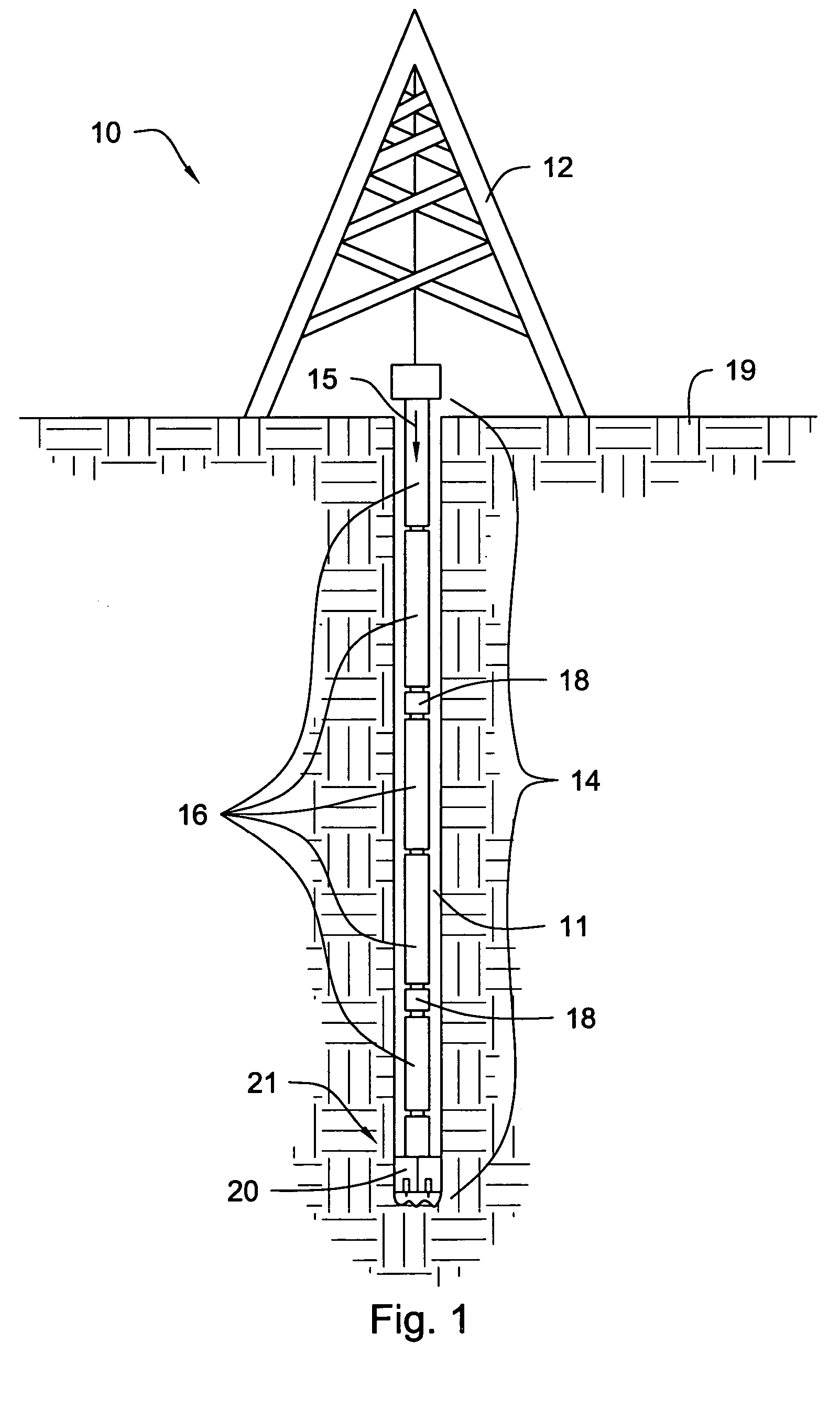
[0013]The present invention is a method and system for effectively cooling electrical components in a downhole environment. Specifically, the present invention contemplates a substantially cylindrical housing integral to a drill string that houses electrical components therein. Unlike prior art systems, however, the electrical components may reside within a wall of the housing such that the wall functions to insulate and protect the components from harmful effects downhole. The wall may further comprise a hollow passageway proximate the electrical components, where the hollow passageway is adapted to accommodate and promote a flow of drilling fluid therethrough.
[0014]A thermoelectric cooling device in accordance with the present invention may be secured to an electrical component and exposed to the hollow passageway such that a flow of drilling fluid through the passageway directly contacts a surface of the cooler. In this manner, the flow of fluid acts as a heat sink to promote efficient heat transfer from the electrical component to an external location. Exposed portions of sensitive electrical components may be substantially encapsulated by a potting material, such as silicon rubber, to further protect the components from hostile effects downhole without compromising the efficiency of the thermoelectric heat transfer disclosed and claimed herein.

Problems solved by technology

Unlike prior art systems, however, the electrical components may reside within a wall of the housing such that the wall functions to insulate and protect the components from harmful effects downhole.

Method used


Image

  • Method and system for cooling electrical components downhole
  • Method and system for cooling electrical components downhole
  • Method and system for cooling electrical components downhole

Examples


Embodiment Construction

[0038]The present invention may be embodied in other specific forms without departing from its spirit or essential characteristics. The described embodiments are to be considered in all respects only as illustrative and not restrictive. The scope of the invention is, therefore, indicated by the appended claims rather than by the foregoing description. All changes that come within the meaning and range of equivalency of the claims are to be embraced within their scope.

[0039]Many of the functional units described in this specification have been labeled as modules, in order to more particularly emphasize their implementation independence. For example, modules may be implemented in software for execution by various types of processors. An identified module of executable code may, for instance, comprise one or more physical or logical blocks of computer instructions that may, for instance, be organized as an object, procedure, or function. Nevertheless, the executables of an identified m...


PUM


Abstract

A method and system that uses the flow of drilling fluid to cool electrical components in a downhole environment. A substantially cylindrical housing comprises a wall which houses at least one electrical component directly coupled to a thermoelectric cooling device. An opposing surface of the thermoelectric cooling device contacts a flow of drilling fluid through a hollow passageway in the wall. The flow of drilling fluid acts as a heat sink to transfer heat from the cooling device to a remote location. In this manner, heat is efficiently and directly transferred from the electrical component to the cooling device to the drilling fluid, while the location of the present system within a wall of the housing enables reliable protection of sensitive electrical components from hostile effects downhole.

Description

BACKGROUND OF THE INVENTION[0001]1. Field of the Invention[0002]The present invention relates to methods and systems for cooling electrical components in a downhole environment and, more particularly, to methods and systems utilizing a flow of drilling fluid to cool electrical components.[0003]2. Background and Related Art[0004]The goal of accessing data from a drill string has been expressed for more than half a century. As exploration and drilling technology has improved, this goal has become more important in the industry for successful oil, gas, and geothermal well exploration and production. For example, to take advantage of the several advances in the design of various tools and techniques for oil and gas exploration, it would be beneficial to have real time data such as temperature, pressure, inclination, salinity, etc. Several attempts have been made to devise a successful system for accessing such drill string data. However, due to the complexity, expense, and unreliability...

Claims


Application Information

Patent Timeline
Patent Type & Authority Patents(United States)
IPC IPC(8): F25B21/02
CPCE21B47/011H01L35/00F25B21/02E21B41/0085E21B47/017H10N10/00E21B47/0175
Inventor HALLFOX, JOE
Owner SCHLUMBERGER TECH CORP
Why Eureka
Try Eureka