Supercharge Your Innovation With Domain-Expert AI Agents!

Fuel tube

a technology of fuel tubes and cylinders, applied in the field of fuel tubes, can solve the problems of reduced fuel permeability of fuel tubes, high fuel permeability, and low flexibility of fuel tubes, and achieve the effect of low fuel permeability and high flexibility

Inactive Publication Date: 2007-12-18
TOYODA GOSEI CO LTD
View PDF18 Cites 5 Cited by
  • Summary
  • Abstract
  • Description
  • Claims
  • Application Information

AI Technical Summary

Benefits of technology

The invention provides a fuel tube that has low fuel permeability and high flexibility. It is made by laminating two layers of resin compositions containing different resins and additives. The layers are self-bonded without the need for an adhesive agent. This results in a fuel tube that has good barrier properties and flexibility.

Problems solved by technology

Although fuel permeability of the fuel tube can be reduced when a low fuel permeability resin such as a polyphenylene sulfide resin (hereinafter referred to as PPS resin) or a polymetaxylylene adipamide resin (hereinafter referred to as MXD6 resin) is used for forming the fuel tube, the fuel tube lacks flexibility because a material low in fuel permeability is generally high in elastic modulus.
In this method, however, fuel permeability becomes high.
It is however impossible to obtain sufficient interlayer adhesive power between the inner layer and the outer layer self-bonded to each other by direct contact because adhesion between the material of the inner layer and the material of the outer layer in the fuel tube produced by lamination in the related art low.

Method used


Image

  • Fuel tube
  • Fuel tube
  • Fuel tube

Examples


examples

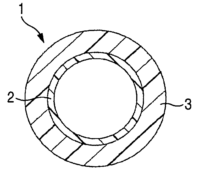
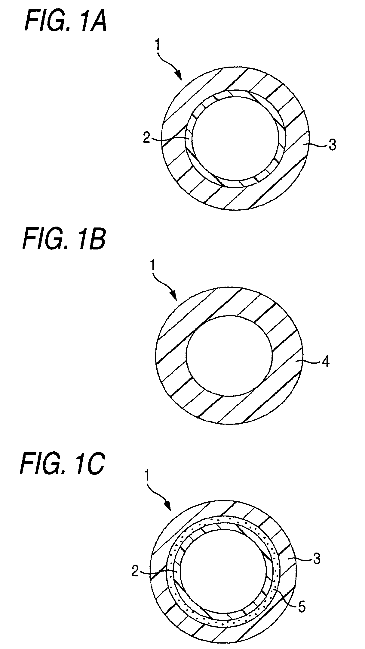
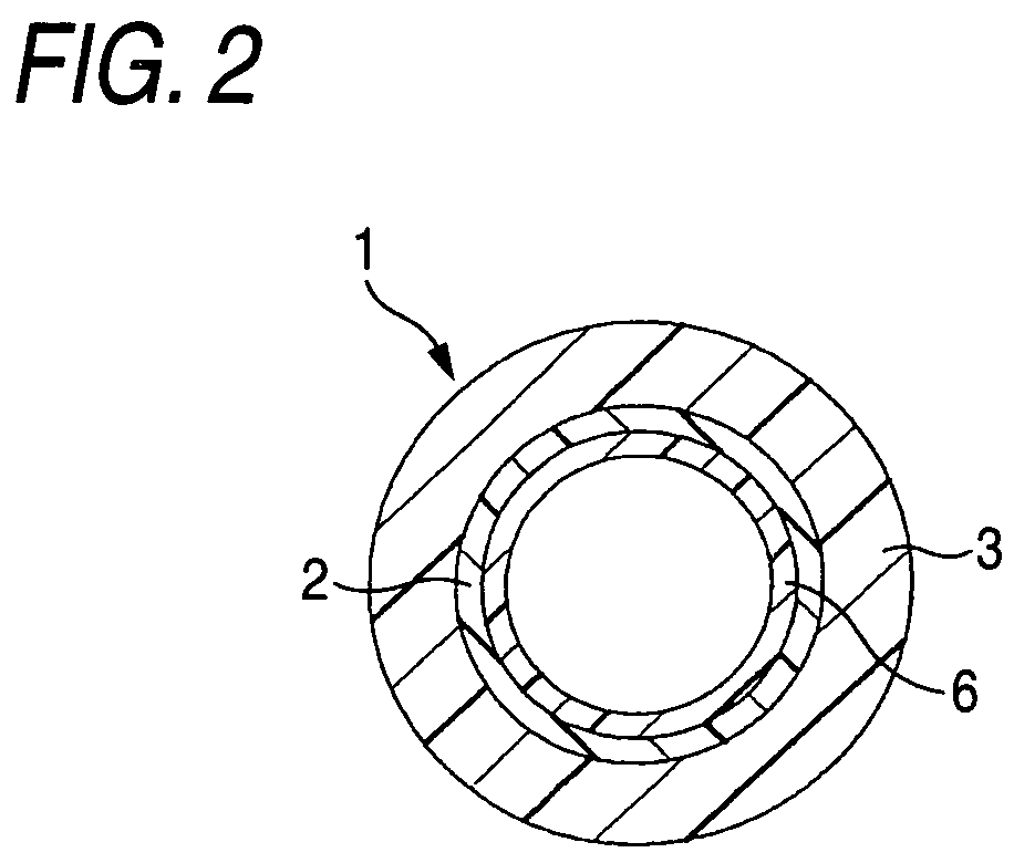
[0032]Resin compositions shown in Tables 1 to 4 were used as Examples and Comparative Examples. A fuel tube 1 having an inner diameter of 6 mm and an outer diameter of 8 mm as shown in FIGS. 1A to 1C was produced from each of the resin compositions. FIG. 1A shows the case where the inner layer 2 and the outer layer 3 are laminated so as to be bonded to each other without interposition of any adhesive agent. This case corresponds to each of Examples 1-1 to 1-6, Examples 2-1 to 2-6 and Comparative Examples 4 and 5. FIG. 1B shows the case where the fuel tube 1 has a single layer 4. This case corresponds to each of Comparative Examples 1-1 to 1-3, Comparative Examples 2-1 to 2-3 and Comparative Example 3. FIG. 1C shows the case where the inner layer 2 and the outer layer 3 are laminated substantially through an adhesive agent 5 and bonded to each other by the adhesive agent 5. This case corresponds to Comparative Example 6.

[0033]

TABLE 1Example1-11-21-31-41-51-6Inner layerCompositionPPS ...


PUM

PropertyMeasurementUnit
thicknessaaaaaaaaaa
mol %aaaaaaaaaa
thicknessaaaaaaaaaa

Abstract

A fuel tube including a laminate of an inner layer and an outer layer, the inner layer being made of a resin composition containing a PPS resin (or an MXD6 resin) as a main component but substantially containing no olefin polymer component, the outer layer being made of a resin composition containing a PPS resin (or an MXD6 resin) as a main component and substantially containing an olefin polymer component, wherein the inner layer and the outer layer are laminated so as to be substantially self-bonded to each other without interposition of any adhesive agent.

Description

[0001]This application is based on Japanese Patent Application No. 2004-108580, which is incorporated herein by reference.BACKGROUND OF THE INVENTION[0002]1. Field of the Invention[0003]The present invention relates to a fuel tube in which fuel such as gasoline, alcohol gasoline or sour gasoline flows.[0004]2. Description of the Related Art[0005]There is a demand for a fuel tube having a good balance between the two characteristics of low permeability to fuel such as gasoline and high flexibility for handling property. Although fuel permeability of the fuel tube can be reduced when a low fuel permeability resin such as a polyphenylene sulfide resin (hereinafter referred to as PPS resin) or a polymetaxylylene adipamide resin (hereinafter referred to as MXD6 resin) is used for forming the fuel tube, the fuel tube lacks flexibility because a material low in fuel permeability is generally high in elastic modulus. The easiest method for improving the flexibility is to use a mixture compo...

Claims


Application Information

Patent Timeline
Patent Type & Authority Patents(United States)
IPC IPC(8): F16L11/00B32B1/08B32B27/32F16L11/04F16L11/11
CPCF16L11/04Y10T428/1393F16L2011/047
Inventor WATANABE, KAZUYAKOIKE, MASAKI
Owner TOYODA GOSEI CO LTD
Features
  • R&D
  • Intellectual Property
  • Life Sciences
  • Materials
  • Tech Scout
  • Unparalleled Data Quality
  • Higher Quality Content
  • 60% Fewer Hallucinations
Learn More