Reusable threaded tie down

a threaded tie down and tie down technology, applied in the direction of threaded fasteners, screws, fishing, etc., can solve the problems of design risk, unsuitable for certain applications, and affecting the range of movement of animals

Active Publication Date: 2007-12-18
ERDELY KIRBY G
View PDF5 Cites 23 Cited by
  • Summary
  • Abstract
  • Description
  • Claims
  • Application Information

AI Technical Summary

Benefits of technology

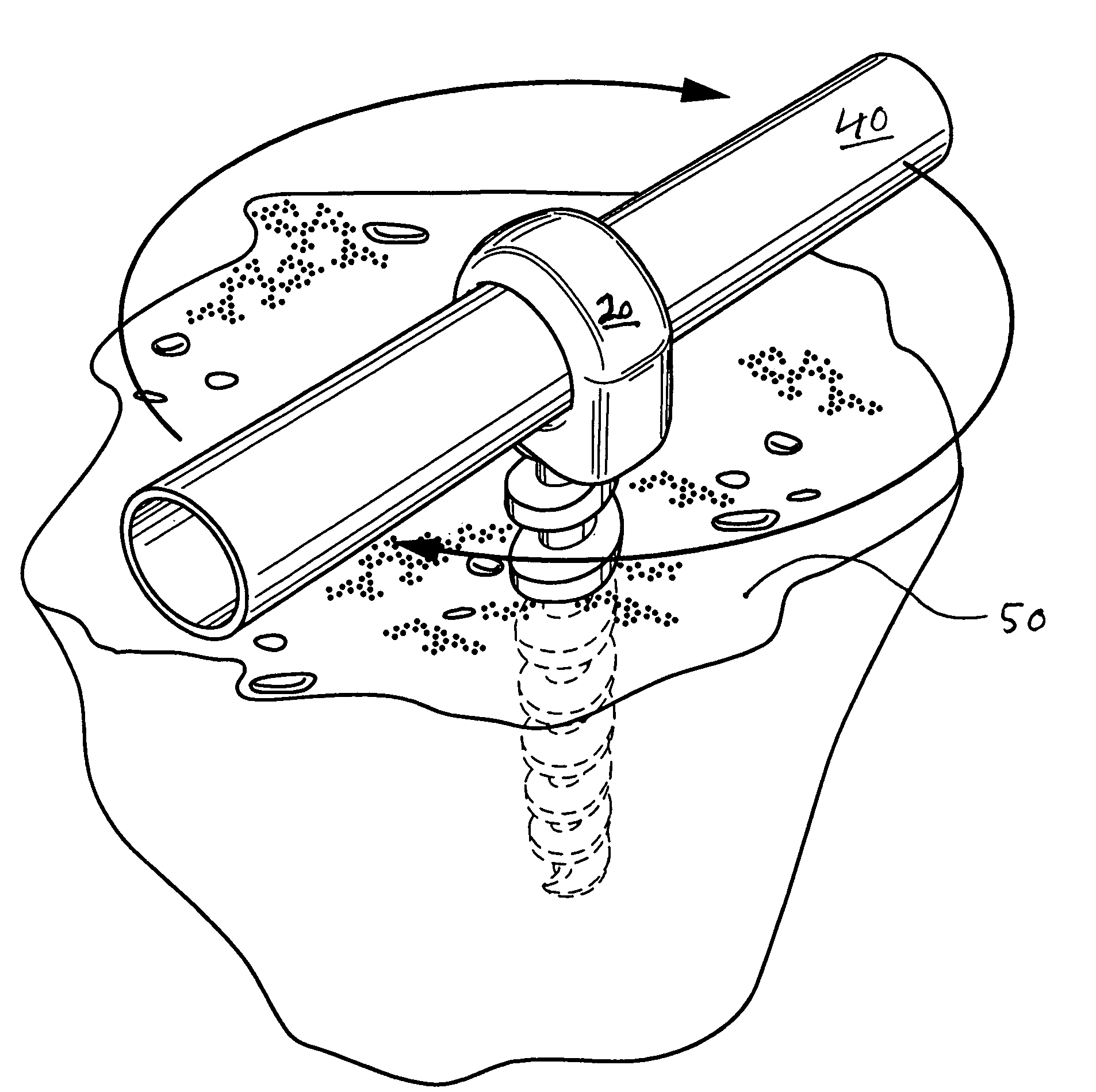
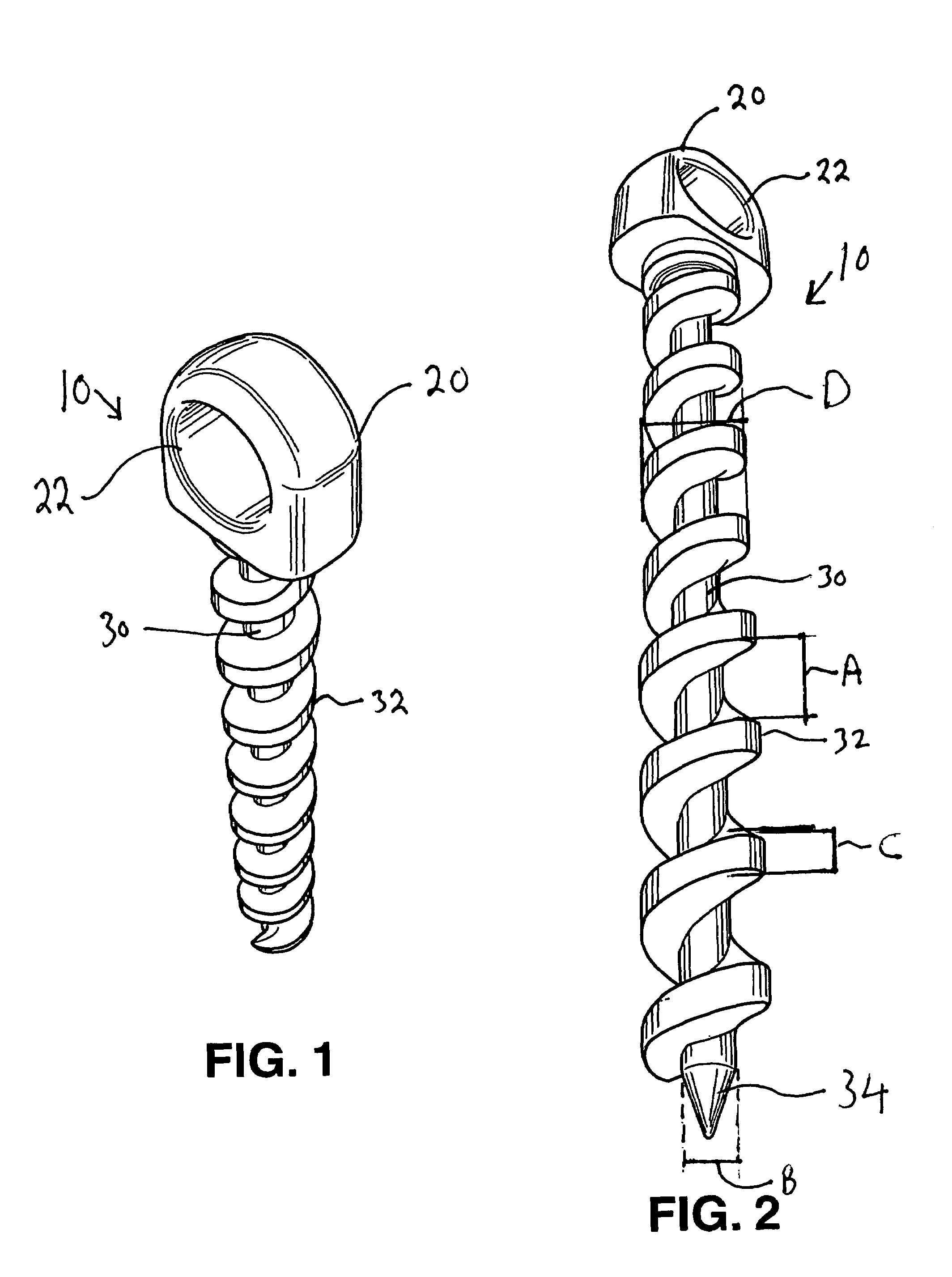
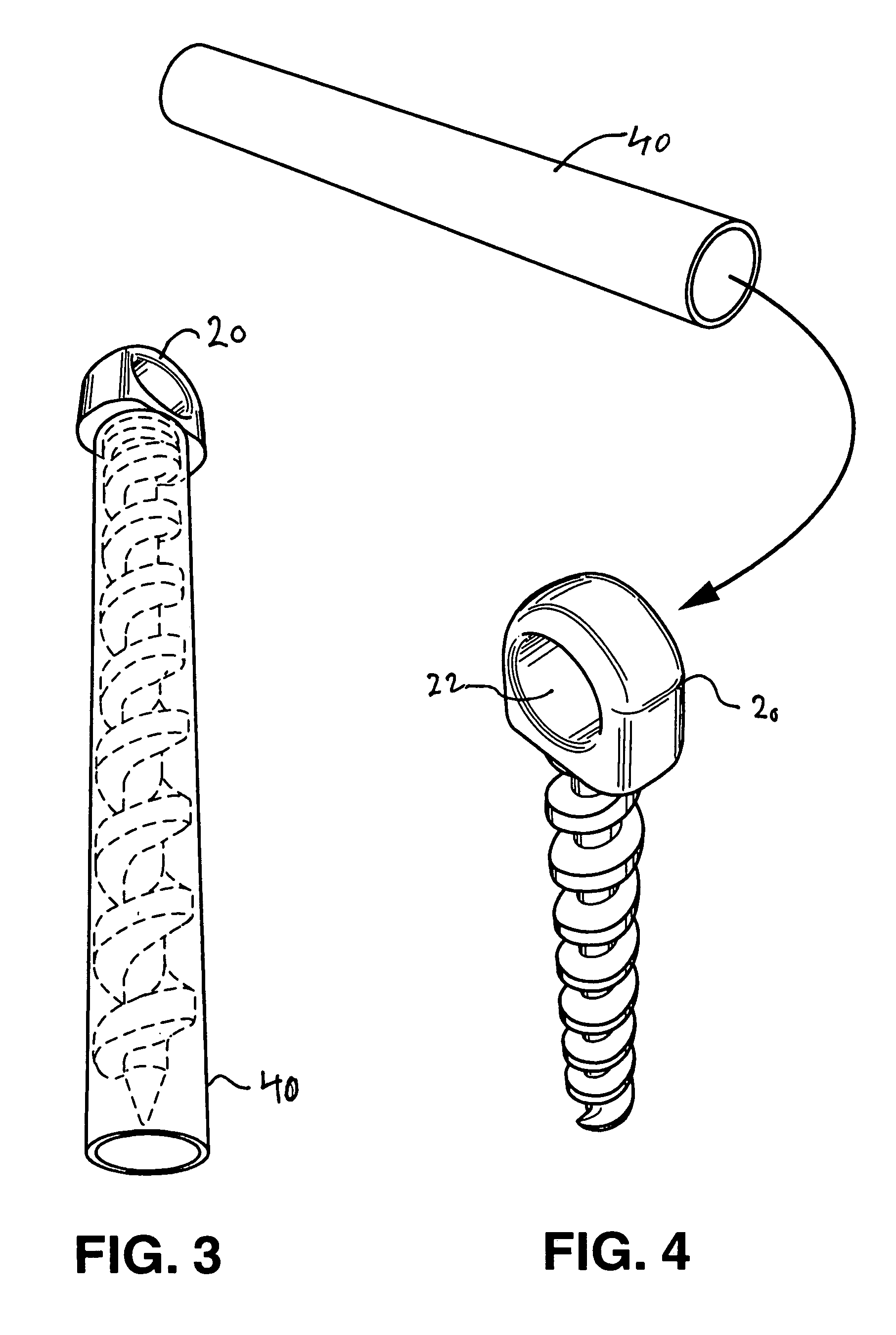
[0006]It is yet another aspect of at least one of the present embodiments to provide for a helical tie down which has a protective sheath surrounding the threaded portion of the tie down, the sheath further providing a handle for insertion through the head of the tie down to facilitate the installation and removal of the tie down from a substrate.
[0009]It is a further aspect of at least one embodiment of the present invention to provide for a helical tie down which is provided from a high impact elastic polycarbonate which allows the tie down to be bent at an angle in excess of 30° and which can be restored to the original shape once the load is removed.

Problems solved by technology

Many of the threaded tie downs in the prior art are provided by metal or rigid plastics which are subject to rust, breakage, or permanent deformation if bent.
Further, the cleat, head, or other attachment point of the tie down frequently has either a shape, contour, or outer dimensions which render it unsuitable for certain applications.
The chain will frequently entangle around the attachment head of the tie down, interfering with the animal's range of movement.
Further, many tie downs have an attachment head which is easily damaged if accidentally struck, while other designs pose an injury risk because of the shape of the head should one trip and / or land on an installed tie down.

Method used


Image

  • Reusable threaded tie down
  • Reusable threaded tie down
  • Reusable threaded tie down

Examples


Embodiment Construction

[0016]Reference will now be made in detail to the embodiments of the invention, one or more examples of which are set forth below. Each example is provided by way of explanation of the invention, not limitation of the invention. In fact, it will be apparent to those skilled in the art that various modifications and variations can be made in the present invention without departing from the scope or spirit of the invention. For instance, features illustrated or described as part of one embodiment can be used on another embodiment to yield a still further embodiment. Thus, it is intended that the present invention cover such modifications and variations as come within the scope of the appended claims and their equivalents. Other objects, features, and aspects of the present invention are disclosed in the following detailed description. It is to be understood by one of ordinary skill in the art that the present discussion is a description of exemplary embodiments only and is not intende...


PUM


Abstract

A reusable tie down is provided having a threaded portion for insertion in soil along with an arcuate head defining an aperture for securing a rope or line to the tie down. The tie down is constructed of a high impact, high tensile strength polycarbonate which may be deformed under a heavy load and then returned to a normal shape by the application of heat.

Description

FIELD OF THE INVENTION[0001]This invention is directed towards a reusable threaded tie down. The tie down includes a protective sheath which can be used as a handle for insertion and removal of the tie down into sand, soil, gravel, and similar materials. The tie down is suitable for a variety of uses including tethers, beach umbrellas, tent stakes, support stakes for new trees and shrubs, and pet tie downs.BACKGROUND OF THE INVENTION[0002]This invention relates to threaded or helical tie downs for use in soil, lawns, campgrounds, and beaches. As seen in reference to U.S. Pat. Nos. D381892 and D492586, the specifications of which are incorporated herein by reference, it is known to provide a threaded structure which includes a bracket or similar structure through which a rope, wire, or similar line may be attached.[0003]Many of the threaded tie downs in the prior art are provided by metal or rigid plastics which are subject to rust, breakage, or permanent deformation if bent. Further...

Claims


Application Information

Patent Timeline
Patent Type & Authority Patents(United States)
IPC IPC(8): B61D45/00
CPCA01K97/10E04H12/2223A45F3/44F16B35/00
Inventor BROWN, DAVID J.
Owner ERDELY KIRBY G
Why Eureka
Try Eureka