
Exhaust gas purification system for internal combustion engine

a technology of exhaust gas purification system and internal combustion engine, which is applied in the direction of engine components, machines/engines, mechanical apparatus, etc., can solve the problems of deteriorating estimation accuracy and achieve the effects of preventing excessive accumulation of exhaust particulate matter, high estimation accuracy, and deteriorating estimation accuracy

Active Publication Date: 2007-12-25
DENSO CORP
View PDF10 Cites 28 Cited by
  • Summary
  • Abstract
  • Description
  • Claims
  • Application Information

AI Technical Summary

Benefits of technology

[0013]It is therefore an object of the present invention to provide an exhaust gas purification system of an internal combustion engine capable of performing regeneration operation of a particulate filter safely and efficiently by accurately estimating accumulation quantity of exhaust particulate matters in the particulate filter, while preventing excessive accumulation of the exhaust particulate matters and achieving appropriate regeneration frequency.
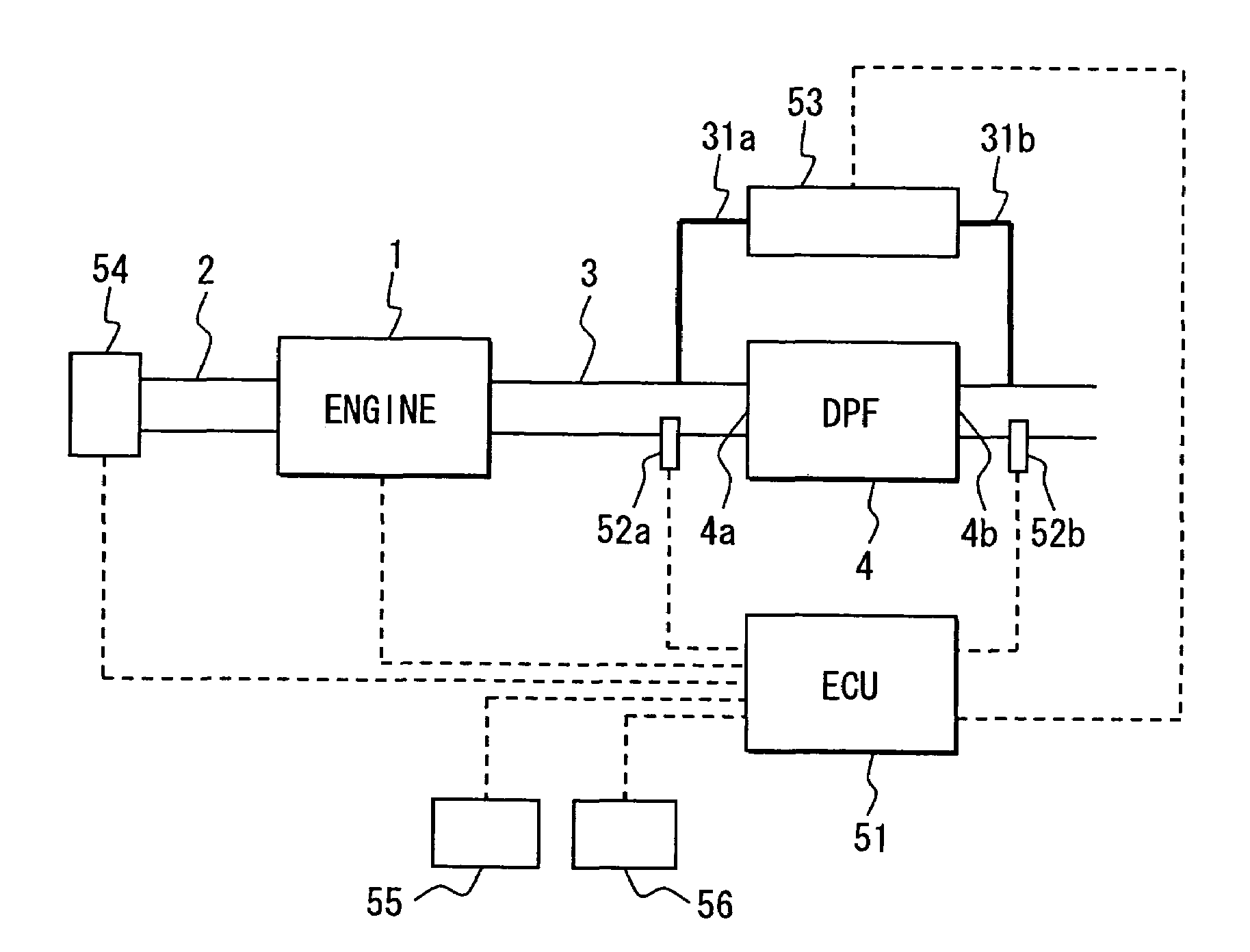
[0015]The accumulation quantity estimation by the first accumulation quantity estimation device is performed when the employment conditions such as a condition that the exhaust gas flow rate is sufficiently large are satisfied. Otherwise, the accumulation quantity estimation by the second accumulation quantity estimation device is performed. Thus, high estimation accuracy is maintained. An estimation error does not accumulate in the accumulation quantity estimation by the first accumulation quantity estimation device. The estimation error is integrated in the accumulation quantity estimation by the second accumulation quantity estimation device, and the estimation accuracy is deteriorated. Therefore, regeneration start accumulation quantities are set in accordance with degrees of the respective estimation errors. Thus, the regeneration can be performed at suitable timing and excessive accumulation of the exhaust particulate matters can be prevented when the estimation is performed by either one of the accumulation quantity estimation devices. Meanwhile, an appropriate regeneration frequency is achieved to prevent deterioration of fuel consumption.

Problems solved by technology

The estimation error is integrated in the accumulation quantity estimation by the second accumulation quantity estimation device, and the estimation accuracy is deteriorated.

Method used


Image

  • Exhaust gas purification system for internal combustion engine
  • Exhaust gas purification system for internal combustion engine
  • Exhaust gas purification system for internal combustion engine

Examples


first embodiment

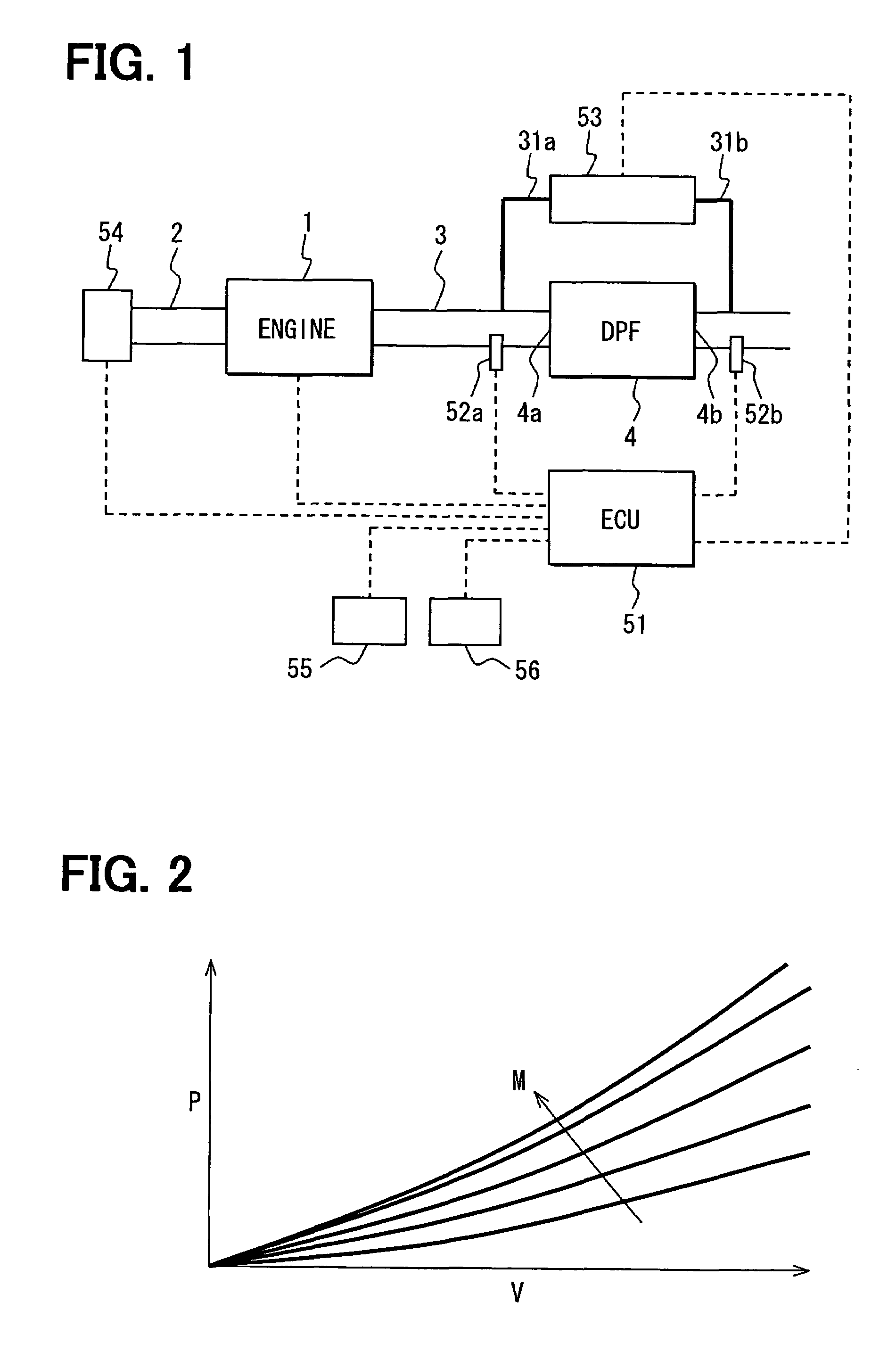
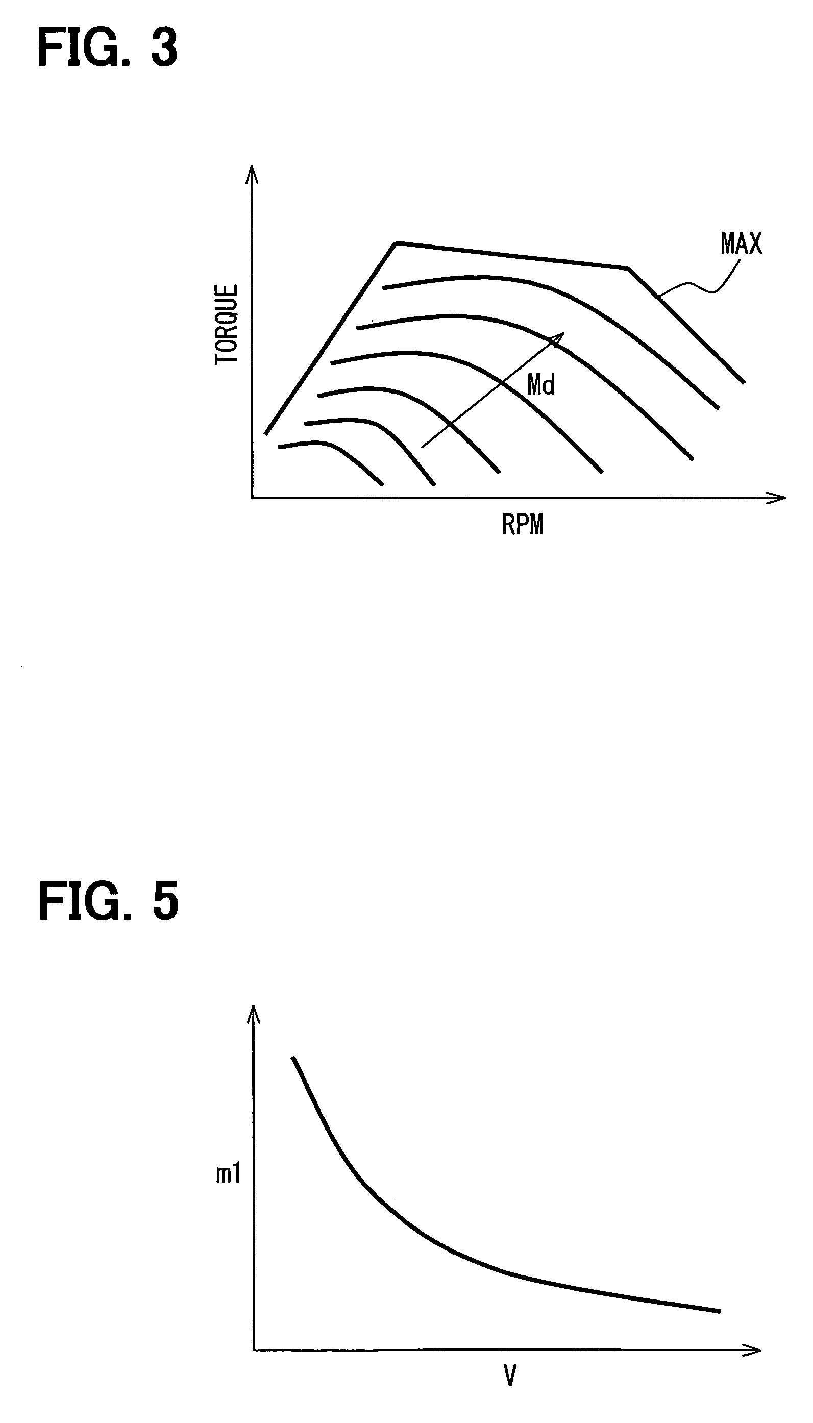
[0061]Processing at Steps S100 to S104 and Step S109 of the flowchart shown in FIG. 6 is the same as that of the If the estimation by the second accumulation quantity estimation device is performed at Step S103, a continuing state of the estimation by the second accumulation quantity estimation device is calculated at Step S104. A reduction quantity ΔM of the regeneration start PM accumulation quantity Mr is calculated in accordance with the continuing state at Step S201. As shown in FIG. 7, the estimation error of the PM accumulation quantity M does not accumulate in the accumulation quantity estimation by the first accumulation quantity estimation device. The estimation error m1 (constant value, here) is subtracted from the limit PM accumulation quantity m to calculate the PM accumulation quantity (m−m1) for starting the regeneration. As shown in FIG. 8, if the estimation device is switched to the second accumulation quantity estimation device, the estimation error accumulates fr...

second embodiment

[0070]In this embodiment, the continuing distance is used as the index indicating the continuation of the estimation by the second accumulation quantity estimation device as in the first or Instead of the continuing distance, the traveling period under the continuation or the integrated value of the fuel injection quantity during the continuation can be used as the index.

[0071]At Step S301, it is determined whether the PM accumulation quantity M estimated by the second accumulation quantity estimation device is “equal to or greater than” the exhaust gas flow rate increase determination accumulation quantity M3. If the result of the determination at Step S301 is “YES,” the processing proceeds to Step S302, where the exhaust gas flow rate increasing operation is performed. Then, the processing returns to Step S100. The estimation error gradually accumulates and the estimation accuracy of the PM accumulation quantity gradually decreases as the estimation by the second accumulation qua...


PUM


Abstract

An exhaust gas purification system has a first accumulation quantity estimation device that estimates an accumulation quantity of exhaust particulate matters collected by a diesel particulate filter (DPF) based on a flowing state of exhaust gas and a second accumulation quantity estimation device that estimates the accumulation quantity based on an operating state of an engine. The first estimation device is employed only when a flow rate of the exhaust gas is equal to or greater than a predetermined value and the engine is in a steady operating state. Otherwise, the second estimation device is employed. The exhaust gas flow rate is increased if the estimation by the second estimation device continues for a long time. Thus, an opportunity to perform the accumulation quantity estimation with the first estimation device is increased, and accumulation accuracy is improved.

Description

CROSS REFERENCE TO RELATED APPLICATION[0001]This application is based on and incorporates herein by reference Japanese Patent Application No. 2005-37160 filed on Feb. 15, 2005.BACKGROUND OF THE INVENTION[0002]1. Field of the Invention[0003]The present invention relates to an exhaust gas purification system of an internal combustion engine. Specifically, the present invention relates to a system having multiple estimation devices that estimate a particulate matter accumulation quantity during a regeneration period of a particulate filter.[0004]2. Description of Related Art[0005]Improvement of exhaust emission of an internal combustion engine of an automobile or the like has been required. Specifically, a diesel engine that uses diesel oil as fuel has to eliminate exhaust particulate matters such as soot in addition to gaseous components such as carbon monoxide, hydrocarbon or nitrogen oxides contained in exhaust gas. Therefore, a particulate filter is located in an exhaust passage to...

Claims


Application Information

Patent Timeline
Patent Type & Authority Patents(United States)
IPC IPC(8): F01N3/00
CPCF01N9/002F01N11/002Y02T10/47F02D2200/0812F01N2900/0422Y02T10/40
Inventor KUBOSHIMA, TSUKASAYAHATA, SHIGETO
Owner DENSO CORP
Learn More