Connector

a technology of connecting rods and connectors, applied in the direction of coupling contact members, coupling device connections, coupling parts, etc., can solve the problems of inability to achieve more miniaturization in height, inability to prevent the permanent set in fatigue of springs, undue increase in locking force, etc., to achieve stable connection, reduce overall height of connectors, and reduce the effect of geometry

Active Publication Date: 2007-12-25
DDK LTD
View PDF32 Cites 24 Cited by
  • Summary
  • Abstract
  • Description
  • Claims
  • Application Information

AI Technical Summary

Benefits of technology

[0023]It is an object of the invention to provide a connector which, in view of the problems of the prior art, can achieve the miniaturization of the connector, narrower pitches and lower geometry or reduced overall height and can obtain stable connection with simple operation and slight operating force without any defective or failed connection, even if a connecting object such as a flexible printed circuit board fitted in the connector is accidentally subjected to undue external forces.

Problems solved by technology

However, it is impossible to more reduce the height of the connector in consideration of strength of the respective members and specifications or customer's demands.
With the construction disclosed in the Patent Literature 1, as the cam portions of the actuator are rotated about one point as a fulcrum, the cam portions could not perform a compact rotation, and the connector could not achieve more miniaturization in height and could not prevent the permanent set in fatigue of springs and undue increase in locking force.
Moreover, applied torque in the clockwise direction could not be certainly stopped or a location at which application of torque should be ended is not clear.
With the construction disclosed in the Patent Literature 2, the miniaturization in height could not be achieved, and a large operating force to be applied to the actuator is required to obtain a desired contact force between the contacts and board or cable so that reliability of contact would be poor.
Moreover, as the actuator is rotated about one point of fulcrum, a compact rotation could not be obtained, and the permanent set in fatigue of springs and undue increase in locking force could not be prevented and applied annular moment or torque could not be certainly stopped.
Moreover, the permanent set in fatigue of the springs and undue increase in locking force could not be prevented, and applied annular moment or torque could not be certainly stopped.
With the construction of the Patent Literature 4 (FIGS. 2 and 6 thereof), as the fitting opening into which the connecting object such as a flexible printed circuit board or the like is inserted is chamfered, when the connecting object is accidentally subjected to an external force in an upward direction, the housing would be likely to be raised so that the contacts also would be raised to make it impossible to obtain stable contacting force (particularly, in the case of contacts positioned on bottom side), resulting into defective or failed connection.
This problem would be particularly acute when a connector is miniaturized, particularly with reduced overall height and accidentally subjected to undue external forces in the case of rotating an actuator or pivoting member on the opposite side of the fitting opening.

Method used


Image

  • Connector
  • Connector
  • Connector

Examples


Embodiment Construction

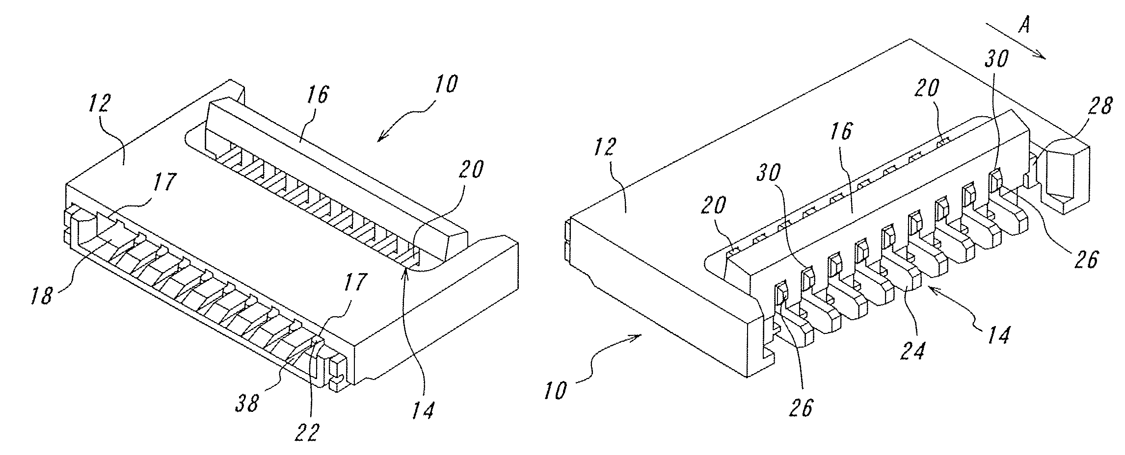
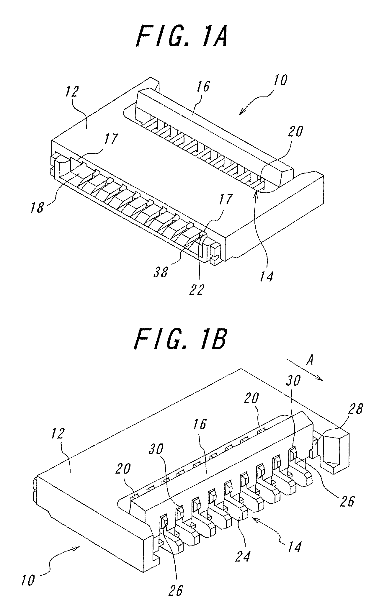
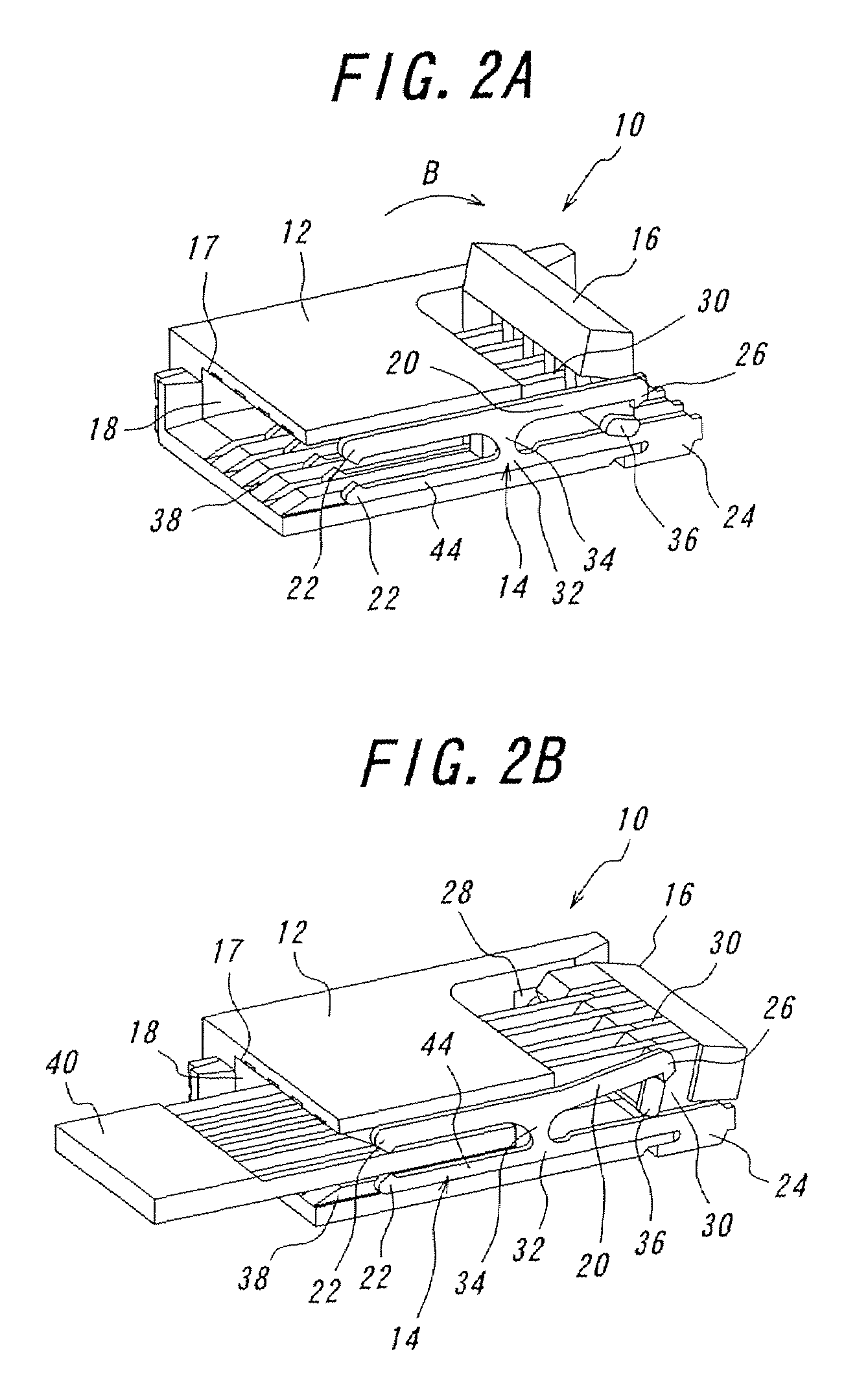
[0111]One embodiment of the connector according to the invention will be explained with reference to FIGS. 1A to 6D. FIG. 1A is a perspective view of the connector according to the invention with a pivoting member opened viewed from the fitting opening side, and FIG. 1B is the connector shown in FIG. 1A viewed from the connection portion side. FIG. 2A is a sectional perspective view of a connector according to the invention taken along one contact, with the pivoting member opened, and FIG. 2B is a sectional perspective view of the connector according to the invention, taken along one contact, with the pivoting member closed after a flexible printed circuit board being inserted. FIG. 3 is a perspective view of the pivoting member. FIG. 4A is a perspective view of a contact having two contact portions, and FIG. 4B is a perspective view of another contact having one contact portion. FIGS. 5A to 5E are views for explaining movements of the urging portion and the rotational axis when the...


PUM


Abstract

A connector includes a plurality of contacts each including a first piece having a contact portion, a pressure receiving portion, and a projection inwardly extending from the pressure receiving portion; a second piece having a connection portion and a fulcrum portion; and an elastic portion for connecting the first piece and the fulcrum portion. The contact portion, elastic portion, fulcrum portion and connection portion are arranged in the form of a crank. A housing is formed with protection walls for preventing its ceiling portion from being raised. The pivoting member is mounted on the housing so that the axis of rotation is moved with its pivotal movement to achieve their compact rotation. With the construction, the connector achieves a miniaturization or reduced overall height, and a stable electrical connection with simple operation and slight operating force without any failed connection even if being subjected to undue external force.

Description

CROSS-REFERENCE TO RELATED APPLICATIONS[0001]This application is a continuation of International Application No. PCT / JP2005 / 013789, filed Jul. 21, 2005, which claims priority to Japanese Patent Application No. 2004-233,197, filed Aug. 10, 2004, both of which are incorporated by reference in their entirety herein and from which priority is claimed.TECHNICAL FIELD[0002]The present invention relates to a connector for use in mobile phones or cellular phones, notebook personal computers, digital cameras or the like, and more particularly to a connector superior in stable electrical connection to a connecting object such as a flexible printed circuit board or flexible flat cable.BACKGROUND ART[0003]In general, connectors for use in mobile phones, charge coupled device (CCD) cameras and the like are much thinner and having contacts arranged in extremely narrow pitches (so-called lighter and more compact connectors). These connectors each mainly comprise a housing, contacts and a slider to...

Claims


Application Information

Patent Timeline
Patent Type & Authority Patents(United States)
IPC IPC(8): H01R13/15H01R12/79
CPCH01R12/78H01R13/62988H01R12/88H01R12/77H01R13/658H01R12/00H01R13/62933H01R12/55H01R12/71
Inventor SUZUKI, MASAYUKI
Owner DDK LTD
Why Eureka
Try Eureka