
Pyramid-shaped near field probe using surface plasmon wave

a near field probe and surface plasmon technology, applied in wave/particle radiation, material analysis, instruments, etc., can solve the problems of reducing the intensity of the traveling wave b>20/b>, difficult light progression, and limited optical information storage schem

Inactive Publication Date: 2007-12-25
SAMSUNG ELECTRO MECHANICS CO LTD
View PDF4 Cites 6 Cited by
  • Summary
  • Abstract
  • Description
  • Claims
  • Application Information

AI Technical Summary

Benefits of technology

[0023]In this case, the present invention allows only a waveguide mode of TM00 to exist at the aperture of the dielectric member by eliminating the end of any one of the metal films that are symmetrically coated on two predetermined sides of four sides of the dielectric member while being spaced apart from each other.

Problems solved by technology

However, such an optical information storage scheme is limited in recording high density information in an advanced information storage device requiring high density recording due to the refractive limit of light, etc.
However, the above-described optical fiber probe 16 using the optical fiber is disadvantageous in that, if a traveling wave 20 propagates into the conical optical fiber 14 and reaches a region near a diameter having a size similar to the wavelength of the traveling wave while propagating into the optical fiber 14, as shown in FIG. 5, the progression of light is difficult, so that the intensity of the traveling wave 20 decreases sharply.
However, since the optical fiber probe using an optical fiber constructed as described above has extremely low transmissivity, it has limitations in Signal-to-Noise (S / N) ratio and recording and reproducing speed, so that the optical fiber probe causes a great number of problems when it is used for a high density optical recording apparatus.
Further, the above-described optical fiber probe using an optical fiber is problematic in that, since light guided to the aperture region is basically formed to have multiple modes, such as traverse magnetic modes TM00, TM10 and TM20, it is difficult to form a sharp beam spot on the aperture.
Further, the optical fiber probe using an optical fiber is problematic in that, since it is manufactured in such a way that, after heat processing is executed for the optical fiber, a conical optical fiber is formed by a pulling operation, and a metal film is coated on the conical optical fiber, it is difficult to structurally manufacture the optical fiber probe.

Method used


Image

  • Pyramid-shaped near field probe using surface plasmon wave
  • Pyramid-shaped near field probe using surface plasmon wave
  • Pyramid-shaped near field probe using surface plasmon wave

Examples


Embodiment Construction

[0036]Hereinafter, embodiments of the present invention will be described in detail with reference to the attached drawings.

[0037]Reference now should be made to the drawings, in which the same reference numerals are used throughout the different drawings to designate the same or similar components.

[0038]With reference to FIGS. 6 to 8, the construction and manufacturing process of a pyramid-shaped near field probe according to the present invention are described in detail.

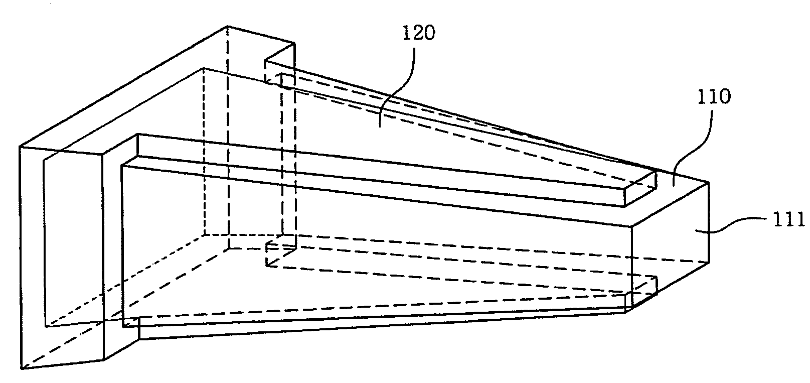
[0039]The near field probe of the present invention allows a surface plasmon wave to propagate to the end of the probe through metal films symmetrically coated on the sides of a pyramid-shaped probe body, thus forming a near field. As shown in FIGS. 6 to 8, the pyramid-shaped near field probe includes a pyramid-shaped probe body 110 and metal films 120.

[0040]The probe body 110, which functions to guide electromagnetic waves that are incident from an external light source and include predetermined waveguide modes, f...


PUM


Abstract

Disclosed herein is a pyramid-shaped near field probe which forms and changes a near field at the aperture of the probe. The pyramid-shaped near field probe of the present invention includes a probe body and metal films. The probe body is constructed in the form of a pyramid using a semiconductor process using a dielectric member and receives an electromagnetic wave. The metal films are symmetrically coated on two predetermined sides of four sides of the probe body while being spaced apart from each other. The pyramid-shaped near field probe allows a surface plasmon wave induced on the surfaces of the metal films due to the electromagnetic wave to progress to the aperture of the probe body through the boundary surface between the probe body and the metal films.

Description

INCORPORATION BY REFERENCE[0001]The present application claims priority under 35 U.S.C. §119 to Korean Patent Application No. 2004-80876 filed on Oct. 11, 2004. The content of the application is incorporated herein by reference in its entirety.BACKGROUND OF THE INVENTION[0002]1. Field of the Invention[0003]The present invention relates, in general, to pyramid-shaped near field probes using surface plasmon waves and, more particularly, to a near field probe, which forms and changes a near field at the aperture of the probe using a surface plasmon wave propagating through the boundary surface between a probe body made of a dielectric and metal films symmetrically coated on the sides of the probe body.[0004]2. Description of the Related Art[0005]Generally, in order to store a greater amount of information per unit area in an optical information storage device, the wavelength of a recording light source must be reduced or the numerical aperture of a condensing lens must be increased. In...

Claims


Application Information

Patent Timeline
Patent Type & Authority Patents(United States)
IPC IPC(8): G01B11/00
CPCB82Y10/00B82Y20/00G11B7/1387G01Q60/22B82Y35/00G01Q80/00G11B9/14
Inventor LAPCHUK, ANATOLIYJEONG, HO SEOPSHIN, DONG IK
Owner SAMSUNG ELECTRO MECHANICS CO LTD
Learn More