Digital camera apparatus with high speed imaging and energy saving features

a digital camera and high-speed imaging technology, applied in the field of digital camera devices, can solve the problems of large power consumption of cameras, and achieve the effect of minimizing power consumption

Inactive Publication Date: 2007-12-25
FUJIFILM HLDG CORP
View PDF12 Cites 13 Cited by
  • Summary
  • Abstract
  • Description
  • Claims
  • Application Information

AI Technical Summary

Benefits of technology

[0007]The present invention solves such a shortcoming of the prior art described above, and provides a digital camera device that would not miss the timing to photograph the subject while minimizing the power consumption.
[0009]The digital camera device according to the present invention is operated through: receiving in the systems control device an operation signal from the operating device; measuring the passage of a predetermined amount of time until the operation signal is supplied while measuring time with the time measuring device; controlling the clock generating device to generate an oscillation frequency higher than normal in response to the pressing operation of the shutter button in the imaging mode; supplying the oscillation frequency generated to the systems control device; performing a control to generate a normal oscillation frequency within the predetermined amount of time; continuing to monitor the operation signal depending on the result of measuring the passage of predetermined amount of time with the time measuring device; and at the same time controlling to generate a frequency lower than the normal oscillation frequency and reducing the power supply. As a result, the digital camera device according to the present invention precisely images an imaging scene desired by the operator and controls the power supply, while increasing the operation speed of the camera according to the pressing operation of the shutter button.

Problems solved by technology

These cameras are known to consume large amounts of power in order to satisfy the demand for high-speed drive and to have an image display function.

Method used


Image

  • Digital camera apparatus with high speed imaging and energy saving features
  • Digital camera apparatus with high speed imaging and energy saving features
  • Digital camera apparatus with high speed imaging and energy saving features

Examples


Embodiment Construction

[0013]Next, a digital camera device in accordance with an embodiment of the present invention will be described in detail with references to the accompanying drawings.

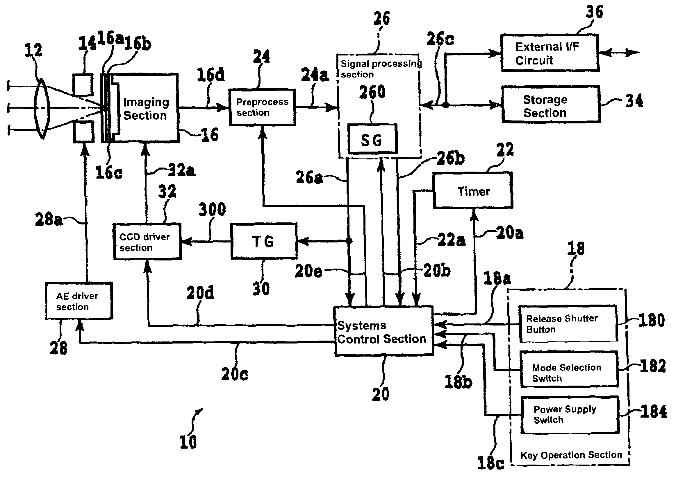
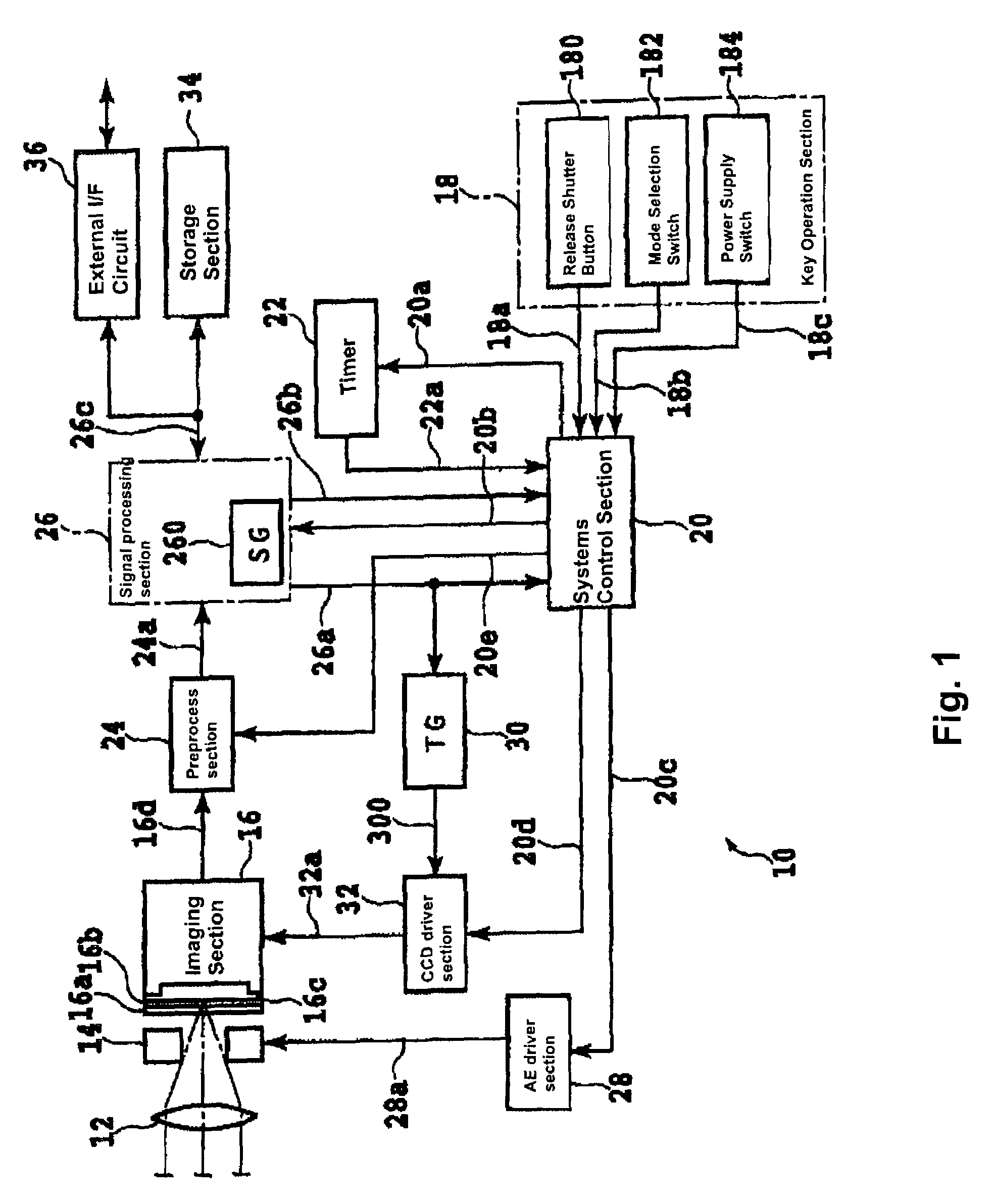
[0014]In the present embodiment, the digital camera device is applied to a toy type digital camera 10 (hereinafter called the “digital camera 10”). Parts that are not directly related to the present invention are omitted from drawings as well as their description. Numbers assigned to various signals correspond to the numbers assigned to connection lines on which the various signals appear.

[0015]The digital camera 10 includes an optical lens system 12, a diaphragm mechanism 14, an imaging section 16, a key operation section 18, a systems control section 20, a timer 22, a preprocessing section 24, a signal processing section 26, an AE (automatic exposure) drive circuit 28, a timing signal generating (TG: timing signal generator) section 30, a CCD (charge coupled device) drive circuit 32, a storage section 34 and an exter...


PUM


Abstract

A digital camera 10 includes a systems control section 20. When the systems control section 20 receives any of operation signals from a key operation section 18, the systems control section 20 measures the passage of time with a timer 22, and continues the time measurement for a specified period of time until any of the operation signals is supplied. In an imaging mode, the system controls section 20 generates an oscillation frequency higher than a normal oscillation frequency with a signal generation circuit 260 in response to a button depressing operation of a release shutter button 180, and generates the normal oscillation frequency upon receipt of any one of the operation signals in a specified period of time. The system controls section 20 continues monitoring the operation signals and generates an oscillation frequency lower than the normal frequency to thereby control to lower the power consumption depending on the result of the measurement of the passage of the specified period of time by the timer 22.

Description

BACKGROUND OF THE INVENTION[0001]1. Field of the Invention[0002]The present invention relates to a digital camera device, whose ideal application is a digital camera with a pan focus function or a toy digital camera.[0003]2. Description of Related Art[0004]Digital cameras are devices that convert incident lights into electrical signals and record the image data obtained from the conversion. These cameras are known to consume large amounts of power in order to satisfy the demand for high-speed drive and to have an image display function. In addition, it is generally considered desirable for these cameras to be compact and lightweight so that they can be portable. Consequently, the digital cameras use high-performance batteries and various ingenious ideas are employed to extend their operational time.[0005]In a conventional digital still camera device, the device's operational state is determined with an operational state determination device based upon the status of a mode selection ...

Claims


Application Information

Patent Timeline
Patent Type & Authority Patents(United States)
IPC IPC(8): H04N3/14H04N5/225H04N5/335H04N5/232H04N101/00
CPCH04N5/23241H04N5/232H04N23/651H04N25/134
Inventor ISHII, AKIHIRO
Owner FUJIFILM HLDG CORP
Why Eureka
Try Eureka