

Zoom lens and imaging apparatus
a technology of zoom lens and imaging apparatus, applied in the field of zoom lens, can solve the problems of too large lenses and reflecting components to achieve compact designs, and achieve the effect of increasing the siz
- Summary
- Abstract
- Description
- Claims
- Application Information
AI Technical Summary
Benefits of technology
Problems solved by technology
Method used
Image

Examples
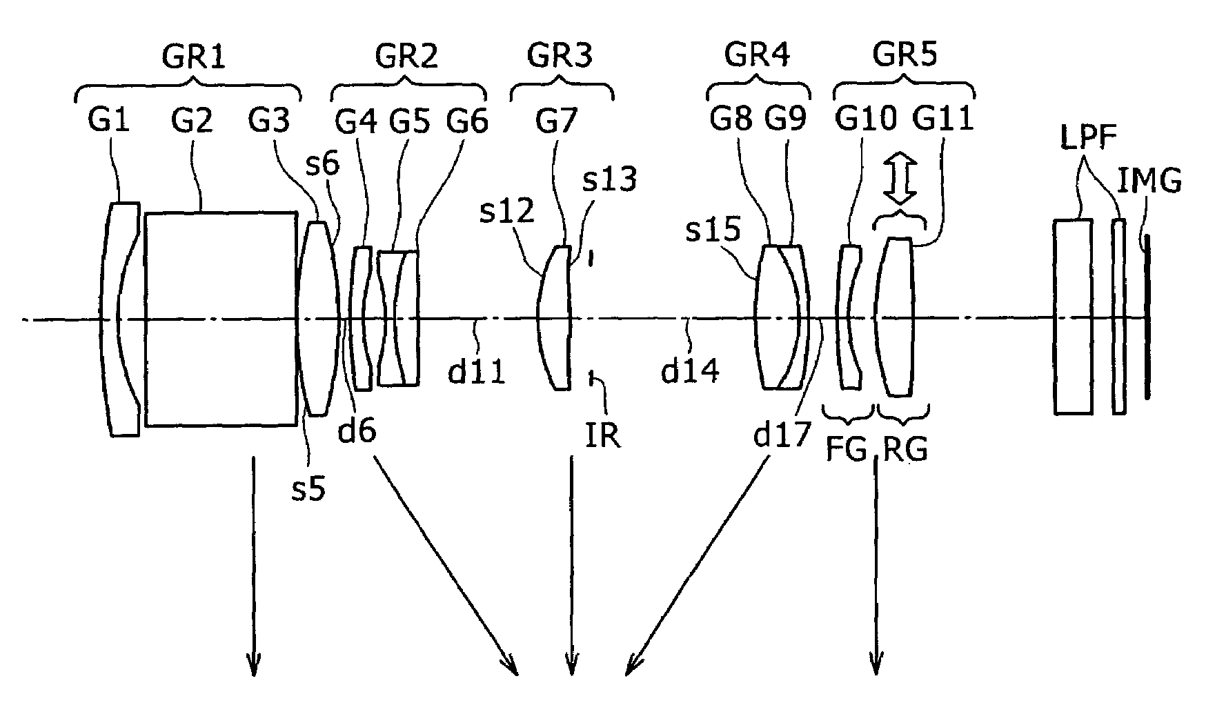
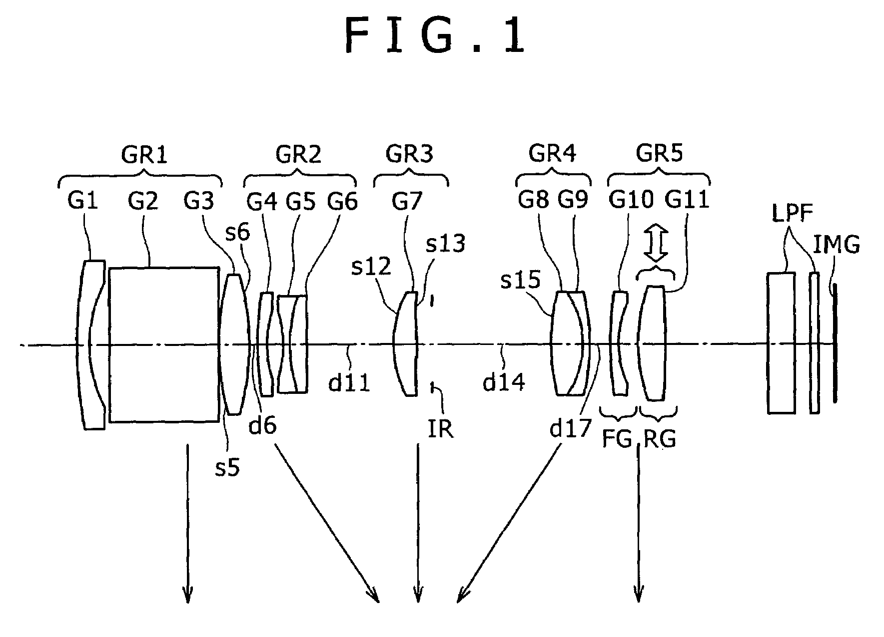
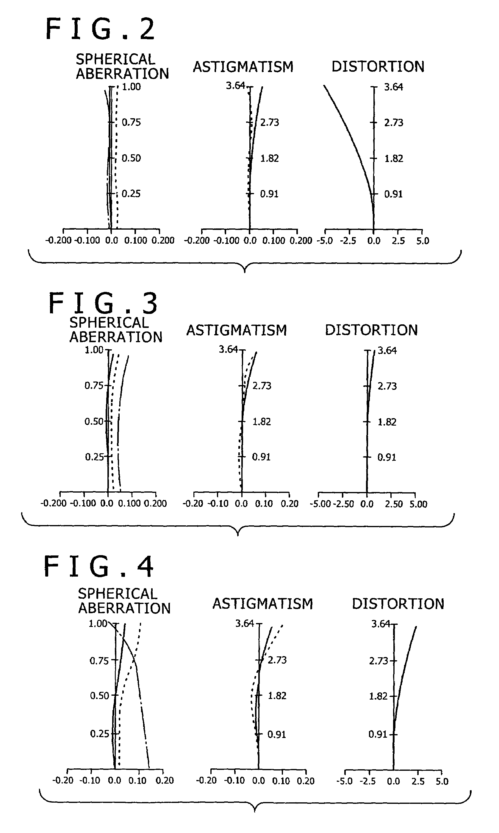
first embodiment
[0059]Table 1 lists numerical values concerning optical elements, which are concrete values adapted to the first embodiment, as part of the first numerical example. In the table, ASP signifies that the surface concerned is an aspheric surface, and INFINITY signifies that the surface concerned is a plane.
[0060]
TABLE 1siridinivi1r1 = 37.313d1 = 0.650n1 = 1.92286v1 = 20.8842r2 = 8.648d2 = 1.3803r3 = INFINITYd3 = 6.900n2 = 1.83500v2 = 42.9844r4 = INFINITYd4 = 0.2005r5 = 11.744(ASP)d5 = 1.988n3 = 1.76802v3 = 49.3006r6 = −18.325(ASP)d6 = variable7r7 = 24.918d7 = 0.500n4 = 1.88300v4 = 40.8058r8 = 6.216d8 = 1.0489r9 = −7.984d9 = 0.500n5 = 1.80420v5 = 46.50310r10 = 8.715d10 = 1.049n6 = 1.92286v6 = 20.88411r11 = 60.123d11 =variable12r12 = 10.486(ASP)d12 = 1.488n7 = 1.77377v7 = 47.20013r13 = −37.305(ASP)d13 = 0.96014r14 = INFINITYd14 =Aperture stopvariable15r15 = 13.0477(ASP)d15 = 2.086n8 = 1.66672v8 = 48.29716r16 = −5.584d16 = 0.500n9 = 1.90366v9 = 31.31017r17 = −12.676d17 =variable18r18 = 34...
second embodiment
[0073]Table 4 lists numerical values concerning optical elements as part a second numerical example, wherein the numerical values are concrete values adapted to the
[0074]
TABLE 4siridinivi1r1 = 40.301d1 = 0.650n1 = 1.92286v1 = 20.8842r2 = 14.578d2 = 1.9003r3 = INFINITYd3 = 11.560n2 = 1.90366v2 = 31.3104r4 = INFINITYd4 = 0.2005r5 = 15.443(ASP)d5 = 2.238n3 = 1.69350v3 = 53.2016r6 = −32.170(ASP)d6 = variable7r7 = 111.075d7 = 0.500n4 = 1.88300v4 = 40.8058r8 = 8.671d8 = 0.9929r9 = −35.625d9 = 0.450n5 = 1.78590v5 = 43.93410r10 = 9.866d10 = 1.199n6 = 1.92286v6 = 20.88411r11 = −103.576d11 = 0.35012r12 = −16.275d12 = 0.500n7 = 1.83500v7 = 42.98413r13 = 80.452d13 =variable14r14 = 12.814(ASP)d14 = 1.596n8 = 1.58313v8 = 59.46115r15 = −29.038(ASP)d15 = 0.92016r16 = INFINITYd16 =Aperture stopvariable17r17 = 11.931(ASP)d17 = 2.270n9 = 1.58313v9 = 59.46118r18 = −8.265d18 = 0.450n10 = 1.80518v10 = 25.45619r19 = −14.682d19 =variable20r20 = 82.821d20 = 0.500n11 = 1.90366v11 = 31.31021r21 = 7.401d21 = 1...
third embodiment
[0086]Table 7 lists as part of a third numerical example numerical values concerning optical elements that are concrete values adapted to the
[0087]
TABLE 7siridiNivi1r1 = 30.837d1 = 0.650n1 = 1.92286v1 = 20.8842R2 = 8.011d2 = 1.5503r3 = INFINITYd3 = 7.000n2 = 1.88300v2 = 40.8054r4 = INFINITYd4 = 0.2005r5 = 11.561(ASP)d5 = 1.970n3 = 1.76802v3 = 49.3006r6 = −23.393(ASP)d6 = variable7r7 = 32.986d7 = 0.500n4 = 1.88300v4 = 40.8058r8 = 6.282d8 = 0.9659r9 = −12.547d9 = 0.500n5 = 1.80420v5 = 46.50310r10 = 7.488d10 = 1.052n6 = 1.92286v6 = 20.88411r11 = 30.403d11 =variable12r12 = 11.113(ASP)d12 = 1.536n7 = 1.69350v7 = 53.20113r13 = −22.861(ASP)d13 = 0.96014r14 = INFINITYd14 =Aperture stopvariable15r15 = 10.041(ASP)d15 = 2.148n8 = 1.58313v8 = 59.46116r16 = −5.654d16 = 0.500n9 = 1.80610v9 = 33.26917r17 = −10.859d17 =variable18r18 = −14.670d18 = 0.500n10 = 1.84666v10 = 23.78519r19 = 8.802d19 = 1.23020r20 = 19.423(ASP)d20 = 2.056n11 = 1.48749v11 = 70.44121r21 = −7.984d21 = 5.34622r22 = INFINITYd22...
PUM
 Abstract
Description
Claims
Application Information