Error management

a technology for error management and error detection, applied in error detection/correction, instruments, computing, etc., can solve the problems of limiting post's diagnostic capabilities, one or more server domains will crash, and the approach has its disadvantages, so as to increase the availability of a server system

Active Publication Date: 2007-12-25
ORACLE INT CORP
View PDF27 Cites 28 Cited by
  • Summary
  • Abstract
  • Description
  • Claims
  • Application Information

AI Technical Summary

Benefits of technology

[0004]The present invention provides a computer system, a method of operating a computer system and a program product that can enable increased availability of a server system in the presence of dynamically detected hardware errors.
[0006]By providing a diagnostic engine to identify a faulty field replaceable unit to be deconfigured, greater reliability with regard to the identification of a faulty unit can be achieved.

Problems solved by technology

In a conventional computer system, when a hardware error occurs, one or more server domains will crash.
Typically, this can result in one or more error messages being printed on a console, and eventually the affected domain(s) will reboot.
However, this approach has its disadvantages.
However, users often set the diagnostic level of POST to a low value thus restricting POST's diagnostic capabilities.
Thus, even after a domain reboots, there is no guarantee that the fault has been isolated and will not recur.
POST may also not detect the error, which might have been triggered by some specific sequence of events.
Also, information regarding the crash is typically not saved.

Method used


Image

  • Error management
  • Error management
  • Error management

Examples


Embodiment Construction

[0040]Examples of the present invention will be described hereinafter with reference with to the accompanying drawings.

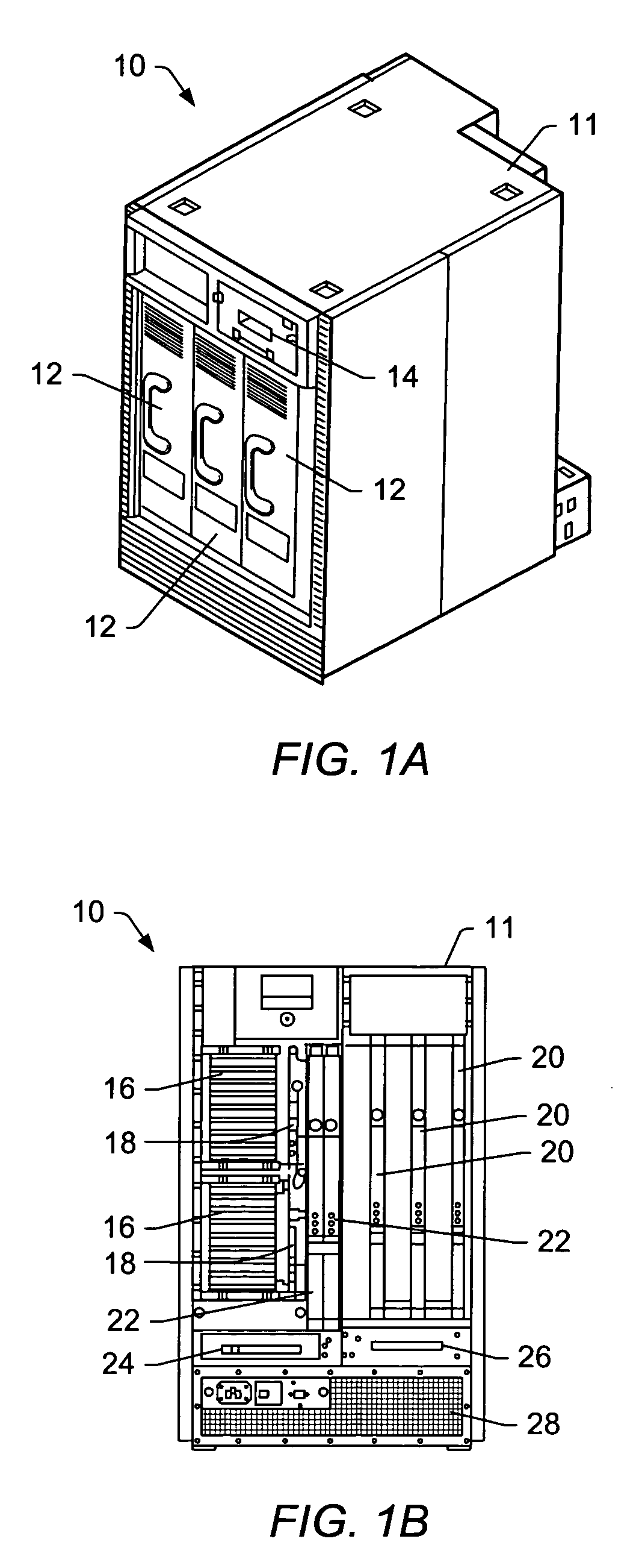
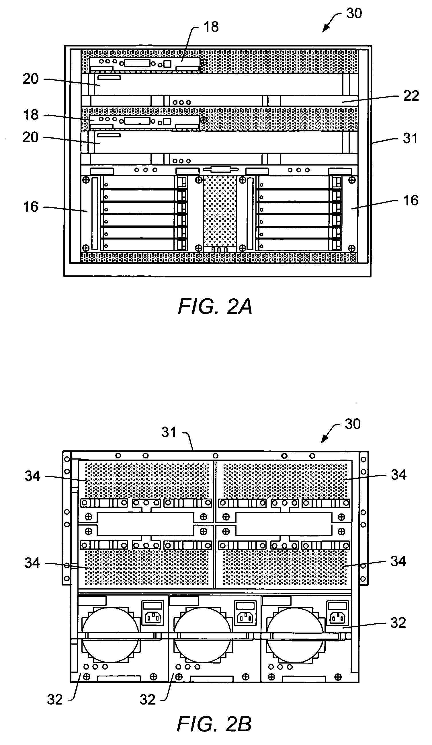
[0041]FIG. 1, which is made up of FIGS. 1A and 1B illustrates one example of a highly available, flexible stand-alone or rack-mountable computer server system. FIG. 1A is a perspective view generally from the front of the server 10 and FIG. 1B is a view from the rear of the server 10.

[0042]The server illustrated in FIG. 1 comprises a number of field-replaceable units (FRUs), which are mountable within a chassis 11. The FRUs are all modules that can be replaced in the field.

[0043]In the example shown in FIG. 1, these modules include up to three system boards 20, which are receivable in the rear face of the chassis 11. Using the system boards, support can be provided, for example, for between 2 and 12 processors and up to 192 Gbytes of memory. Two further modules in the form of I / O boards 16 are also receivable in the rear face of the chassis 11, the I / O boards 16 bei...


PUM


Abstract

A computer system includes a plurality of field replaceable units. A system controller monitors system errors. A diagnostic engine is responsive to the system controller detecting an error to identify a faulty field replaceable unit. A reconfiguration engine can then be operable to deconfigure the faulty field replaceable unit. By providing a diagnostic engine to identify a faulty field replaceable unit to be deconfigured, greater reliability with regard to the identification of a faulty unit can be achieved.

Description

BACKGROUND OF THE INVENTION[0001]The present invention relates to a method and apparatus for facilitating hardware fault management in a computer system, for example a computer server system.[0002]In a conventional computer system, when a hardware error occurs, one or more server domains will crash. Typically, this can result in one or more error messages being printed on a console, and eventually the affected domain(s) will reboot. During this reboot, a Power On Self Test (POST) utility or the like may catch the faulty component(s) and deconfigure that component or components from the system. However, this approach has its disadvantages. When the system restarts, POST has to recreate the error during its diagnostic phase, diagnose the faulty component and deconfigure it out of the system. However, users often set the diagnostic level of POST to a low value thus restricting POST's diagnostic capabilities. Thus, even after a domain reboots, there is no guarantee that the fault has be...

Claims


Application Information

Patent Timeline
Patent Type & Authority Patents(United States)
IPC IPC(8): G06F11/00G06F11/07G06F11/30
CPCG06F11/0712G06F11/0727G06F11/0772G06F11/3055G06F11/3006G06F11/3013G06F11/3031G06F11/079G06F11/0766G06F11/30
Inventor VECOVEN, FREDERIC LOUIS GHISLAIN GABRIELPANICKER, SUNDEEP R.
Owner ORACLE INT CORP
Why Eureka
Try Eureka