Induction liquid pump and magnetic tank scrubber

a liquid pump and magnetic tank technology, applied in the field of liquid pump, can solve the problems of limiting the flexibility of habitat design, the danger of electric power cords, and the obstacle of the functional and aesthetic aspects of the aquatic environment, and achieve the effect of increasing or decreasing attraction

Inactive Publication Date: 2008-01-01
WATKINS CHARLES E
View PDF27 Cites 74 Cited by
  • Summary
  • Abstract
  • Description
  • Claims
  • Application Information

AI Technical Summary

Benefits of technology

[0016]A magnetic scrubber includes a power unit having a power unit body casing housing a power induction unit. The power unit produces a magnetic field in response to supplied power which may be varied by the user in either the power and / or polarity of the power unit magnet or electromagnet. A pad unit containing at least one permanent magnet moves in response to the variable magnetic field created by the power unit. When the power unit is held against a first surface of a tank side wall or bottom by an operator, the movable pad unit is held against a second surface of the tank side wall by way of magnetic attraction. The pad unit moves in response to the variations in the force and polarity of the magnetic field created by the power unit. The pad unit includes a rotatable pad section that rotates to scrub the second surface of the tank side wall. The power unit may provide the operator with the ability via a control surface, like a dial, to increase or decrease the attraction between the power unit and the movable pad or the rate of agitation or spin of the movable pad.

Problems solved by technology

However, the cord itself presents an obstacle to the functional and aesthetic aspects of the aquatic environment.
The electric power cord may also present a danger to the habit through a possibility of electrocution.
The power cord found on conventional aquarium water pumps limits flexibility in habitat design.
While a drained aquarium tank may be easily cleaned with a manual scrubbing pad, a full aquarium tank presents a number of cleaning challenges.
However, the elongated handle is subject to flex during use, which decreases control and ease of cleaning.
Further, in larger tanks, the elongated cleaning tool may not be easily manipulated while at the same time adequately viewing the surface to be cleaned.

Method used


Image

  • Induction liquid pump and magnetic tank scrubber
  • Induction liquid pump and magnetic tank scrubber
  • Induction liquid pump and magnetic tank scrubber

Examples


Embodiment Construction

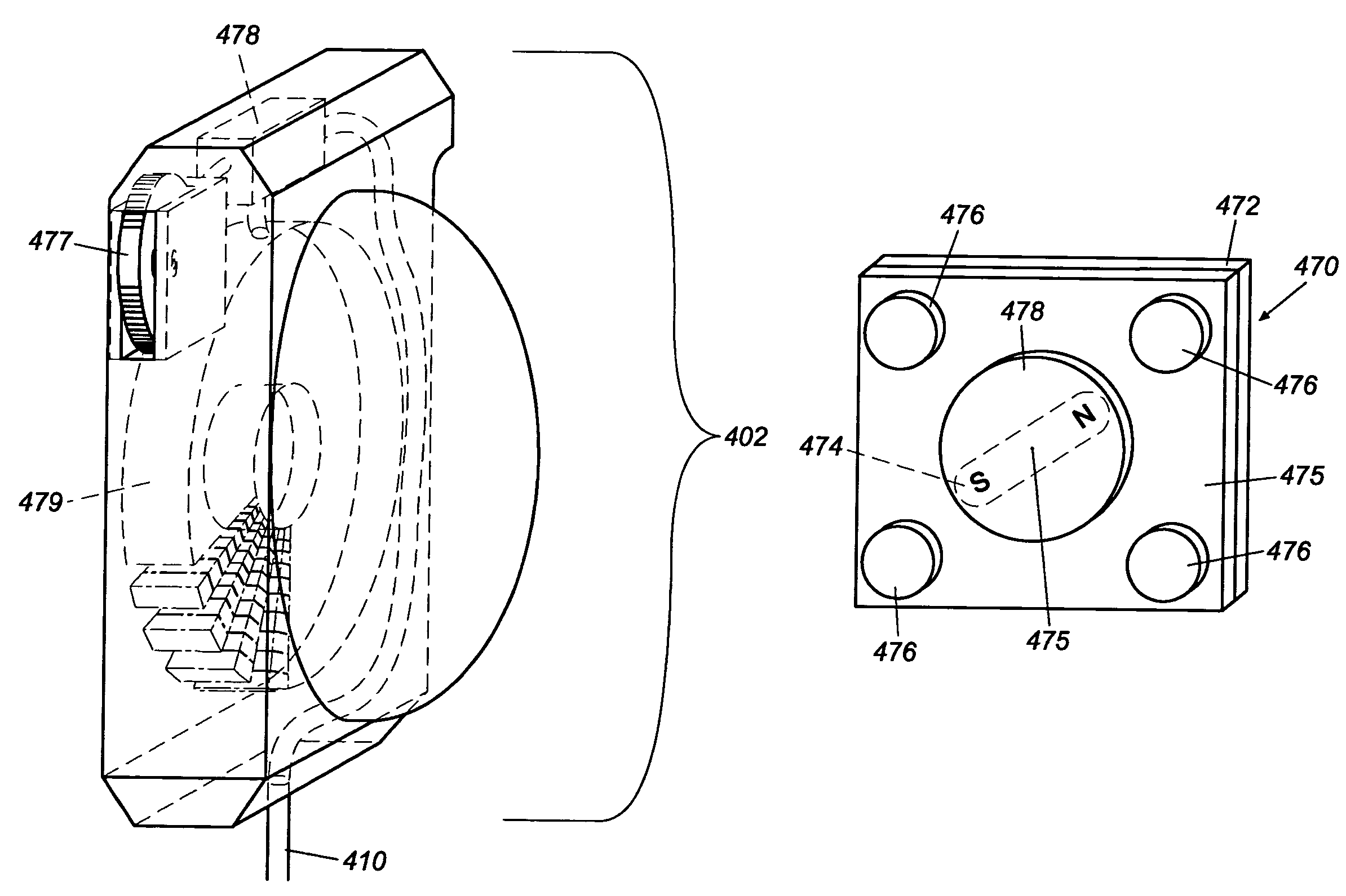
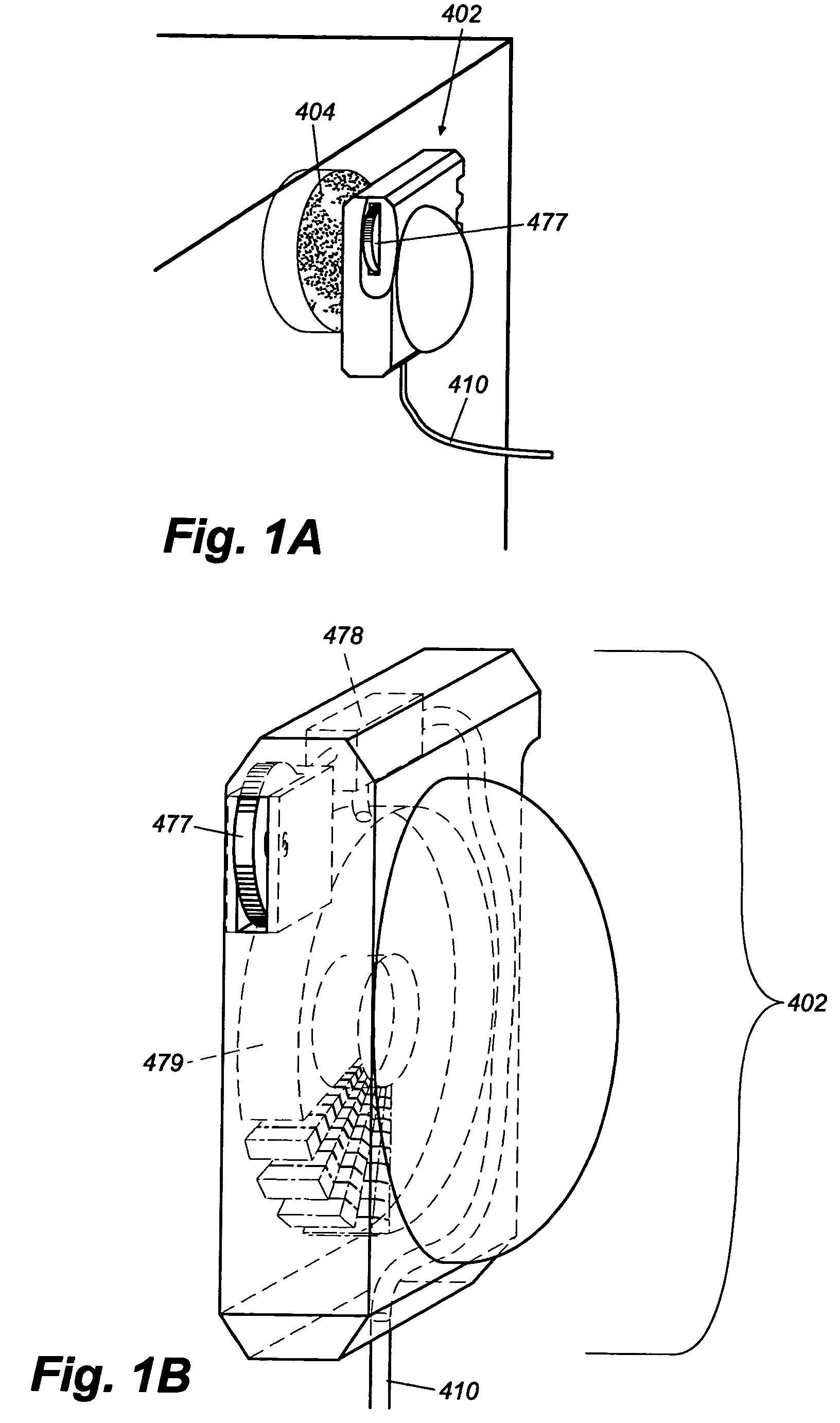
[0053]Referring now to the drawings, and in particular FIG. 1A, wherein like reference numerals are intended to refer to like parts throughout, embodiments of the present invention are shown and described. FIG. 1A illustrates an elevated view of the corner of an aquarium 100 and an electric glass scrubber, comprised of a power unit 402 and pad unit 404, according to the preferred embodiment of the present invention. Power unit 402 is of a size such that it fits easily into an adult human hand, and is comprised of at least one electromagnet (not shown) and control unit (not shown) that produce a variable magnetic field in response to power supplied by a power cord 410. Said variable magnetic field can be controlled in the force of magnetic attraction and / or polarity by way of a dial 477 or other control surface. Said variable magnetic field induces movement in the pad unit 404 by influencing at least one permanent magnet or other suitable material such as a ferrous material that resp...


PUM


Abstract

An induction liquid pump includes a power unit and a circulation unit that are oppositely mountable to a tank with a plurality of fixation units. The liquid pump power unit includes a power induction unit to produce a variable magnetic field. The submersible liquid pump circulation unit includes an impeller unit to agitate or induce liquid flow in response to the variable magnetic field. A magnetic scrubber includes a power unit and a pad unit. The scrubber power unit produces a variable magnetic field in response to supplied power. When the scrubber power unit is held against a first surface of a tank, the scrubber pad unit is held oppositely against a second surface of the tank. The scrubber pad unit moves in response to the variable magnetic field to scrub the second surface of the tank.

Description

[0001]This application claims priority to U.S. Provisional Application No. 60 / 398,517, filed on Jul. 25, 2002, the entire disclosure of which is incorporated by reference herein.TECHNICAL FIELD[0002]The present invention relates generally to the art of liquid pumps, also known as “power heads,” and to the art of tank scrubbers. More particularly, the present invention relates to the art of aquarium water pumps wherein power is transmitted through an aquarium tank wall. The present invention also relates to the art of magnetic tank scrubbers wherein power to agitate the scrubber is transmitted through an aquarium tank wall.BACKGROUND OF THE ART[0003]Aquariums and other simulated environments often require the use of agitated water either to support life and / or to add to environmental aesthetic appeal. In fact, aesthetics are of paramount importance in the creation of a simulated habitat. A properly simulated environment will reduce stress on living creatures and increase owner enjoym...

Claims


Application Information

Patent Timeline
Patent Type & Authority Patents(United States)
IPC IPC(8): A47L1/09A47L1/00A01K63/04F04D13/02
CPCA01K63/047F04D13/027
Inventor WATKINS, CHARLES E.
Owner WATKINS CHARLES E
Why Eureka
Try Eureka