Folding deck mechanism

Inactive Publication Date: 2008-01-01
MTD PRODUCTS
View PDF40 Cites 35 Cited by
  • Summary
  • Abstract
  • Description
  • Claims
  • Application Information

AI Technical Summary

Benefits of technology

[0008]The present invention is characterized by a simple and cost effective system for providing a sectional mower deck which overcomes the aforementioned difficulties associated with the prior art. In accordance with the present invention, there is provided an improved mower deck having a main deck housing and at least one pivoting side wing section wherein the cutting blades remain as fixed components of the main deck housing. The mower deck is supported by the frame of the mowing machine, allowing the mower deck to function as a rigid platform capable of supporting accessory material collection systems, discharge chutes, or optional mulching capability. If desired, the pivoting side wing sections may be raised upwards, thereby presenting the mowing machine with a more narrow profile for passage through narrow width openings and to occupy less space during storage, transport and the like. The pivoting side wing sections can be raised upward by way of electric, hydraulic, or manual means, and can be operated remotely from the operator station of the mowing machine. For safety purposes, means are provided to prevent the cutting blades from rotating when the side wing sections are raised. In contrast to prior art designs wherein the blade spindles remain as fixed components of the pivoting side wing sections, the present invention provides a pivoting mower deck and cutting blade assembly wherein the blade spindles remain as fixed components of the main deck housing. Since the cutting blades remain substantially coplanar to the main deck housing when the side wing sections are raised, the cutting blades themselves are adapte

Problems solved by technology

The drive arrangements and mounting mechanisms for cutting blade structures which pivot in conjunction with the side wing sections tend to be very complex, resulting in relatively high production, maintenance, and repair costs for such prior art machines.
Another problem with prior art designs is that they have not been entirely satisfactory for use with zero-turn-radius (ZTR) mowing machines.
Providing such castor wheel arrangements in a cost effective manner has be

Method used


Image

  • Folding deck mechanism
  • Folding deck mechanism
  • Folding deck mechanism

Examples


Example

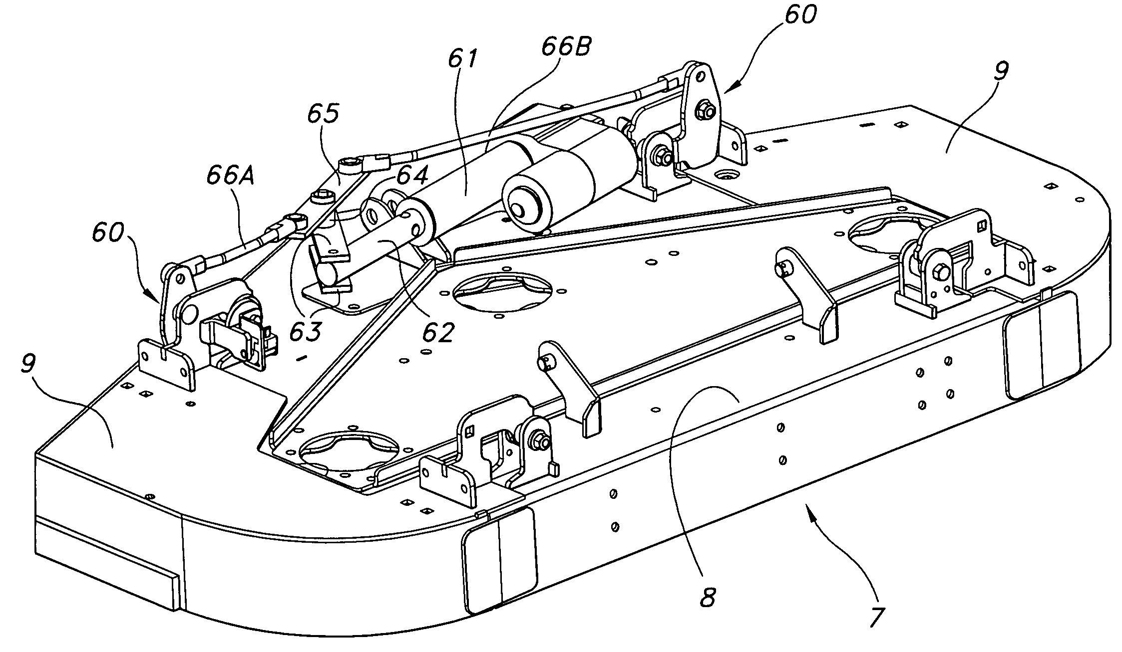
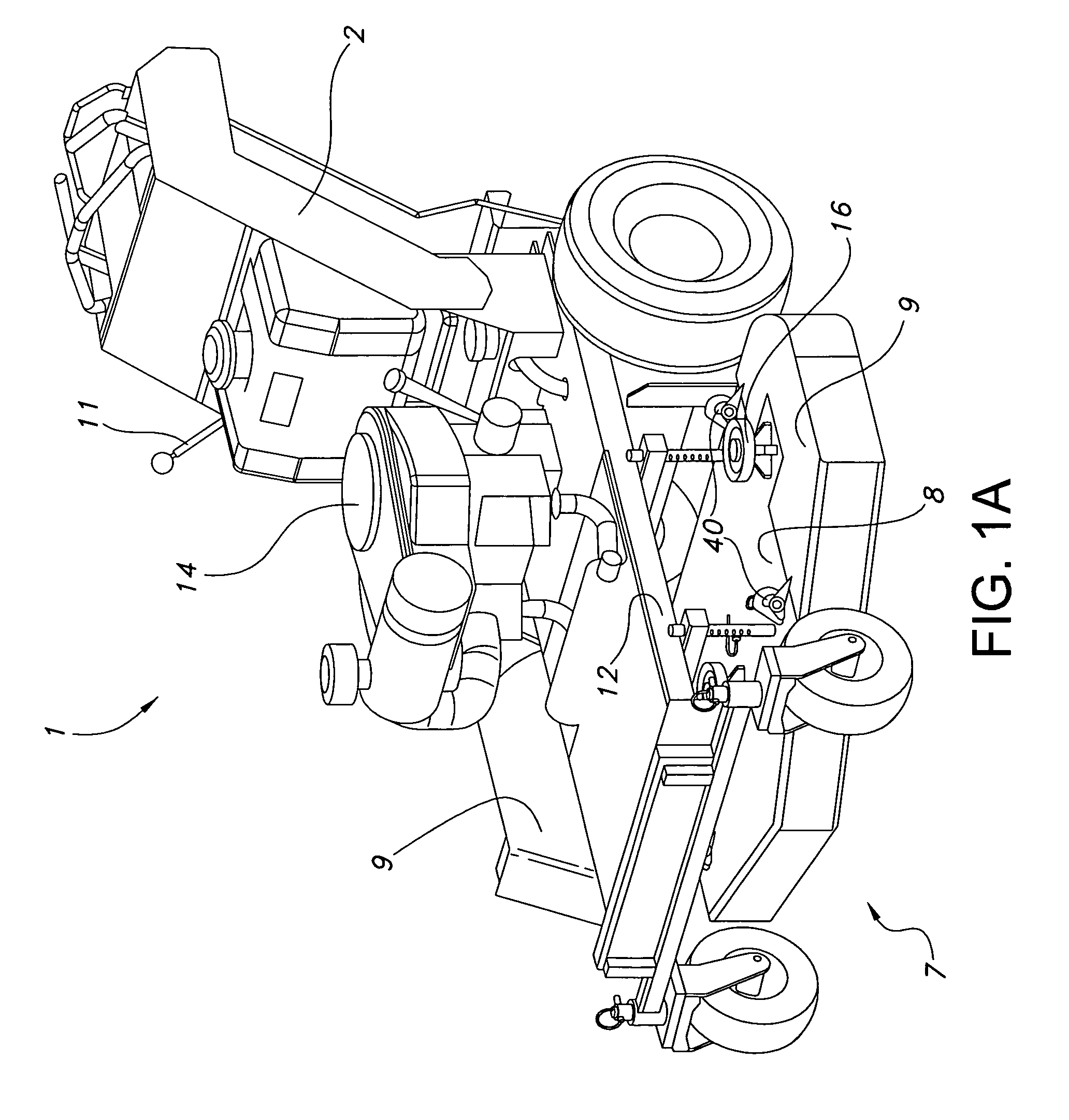
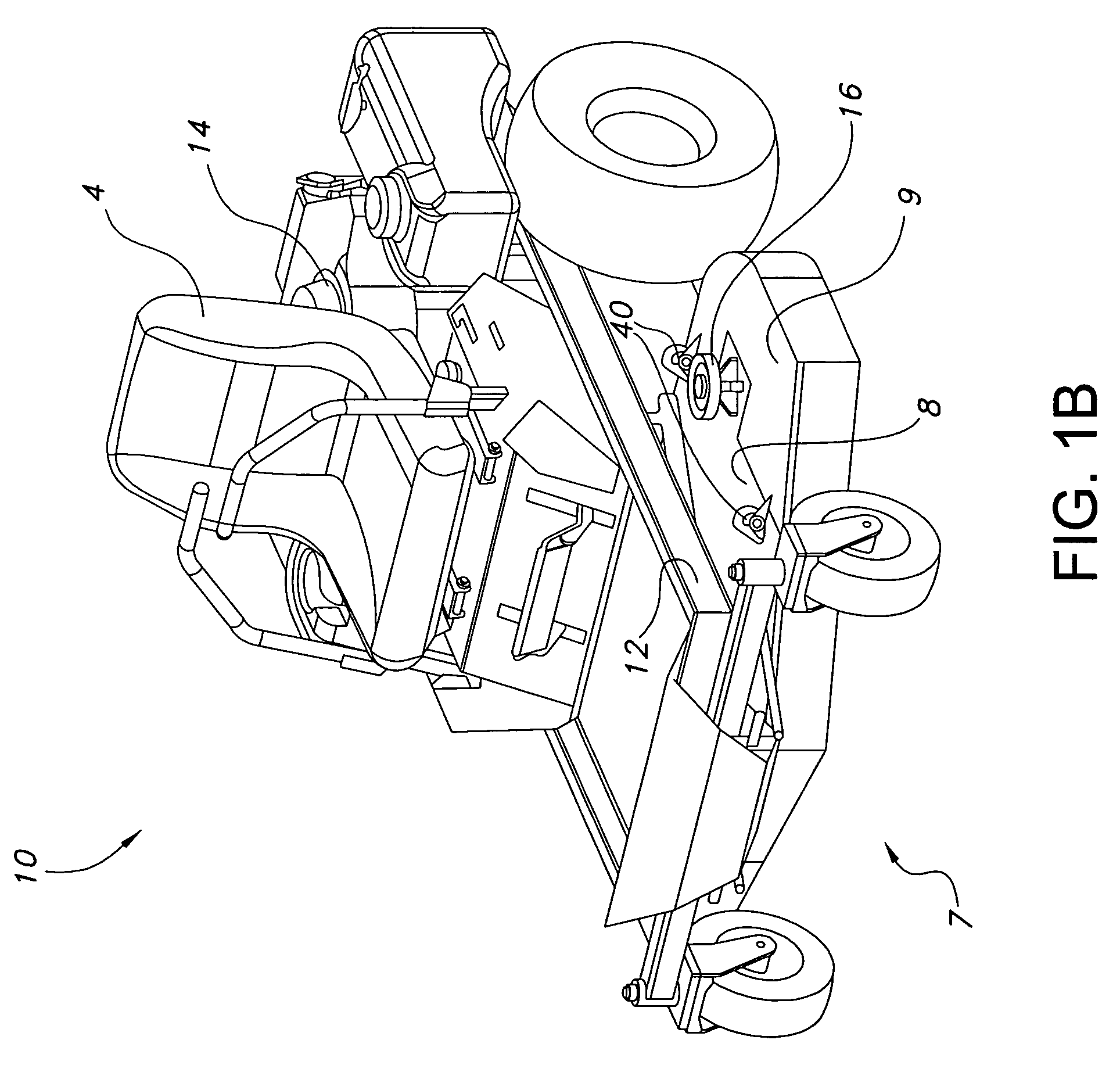
[0017]With reference now to the drawings which illustrate the preferred embodiments of the invention, FIG. 1A shows an exemplary walk-behind lawn mowing machine 1 in accordance with one embodiment of the present invention. FIG. 1B shows an exemplary zero-turn radius (ZTR) mowing machine 10 in accordance with another embodiment of the present invention. The embodiments include a sectional mower deck 7 carried by a support frame 12. The mower deck 7 comprises a main deck housing 8 and a pair of pivoting side wing sections 9. The side wing sections are pivotally attached to opposite sides of the main deck housing, wherein the side wing sections are adapted to pivot upward relative to the main deck housing so as to present a more narrow profile for the mowing machine. A plurality of cutting blade spindles 16 are vertically mounted to the main deck housing 8, wherein the blade spindles are driven by an implement drive means such as an electric blade clutch (not shown) which transmits pow...


PUM


Abstract

A lawn mowing machine having a mower deck with pivoting side wing sections. The pivoting side wing sections can be pivoted upward relative to the main deck housing. When the side wing sections are raised, the mowing machine is presented with a more narrow profile to pass through narrow width openings and to occupy less space during storage, transport and the like. The cutting blade spindles remain as fixed components of the main deck housing and do not pivot upward in conjunction with the side wing sections. When the side wing sections are raised, the cutting blades are adapted to pivot inwardly and underneath the main deck housing so that they do not protrude beyond the sides of the main deck housing. In this way, the mowing machine is adapted to pass through narrow width openings without the operator having to leave the operator station.

Description

CROSS REFERENCE TO RELATED APPLICATIONS[0001]This application claims the priority benefit of U.S. Provisional Patent Application Ser. No. 60 / 609,691 filed Sep. 14, 2004 and U.S. Provisional Patent Application Ser. No. 60 / 708,627 filed Aug. 16, 2005.BACKGROUND OF THE INVENTION[0002]1. Field of Invention[0003]The present invention relates generally to the field of mower decks for riding or walk-behind lawn mowing machines, and more particularly relates to an improved sectional mower deck having pivotal side wing sections which can be raised upwardly so as to create a more narrow profile for the mowing machine.[0004]2. Description of Related Art[0005]Various types of lawn mowing machines having pivotal side wing sections have been developed. The current offerings of such mower decks are typically of the ground following type wherein the side wing sections can be selectively raised or removed to present a more narrow profile for passage through narrow width openings and for storage, tra...

Claims


Application Information

Patent Timeline
IPC IPC(8): A01D34/00
CPCA01D34/661A01D34/64A01D34/78A01D34/828
Inventor EAVENSON, SR., JIMMY N.O'TOOLE, DENNISMATTERN, JEFF
Owner MTD PRODUCTS
Why Eureka
Try Eureka