Corrugated sheet member bending machine

Inactive Publication Date: 2008-01-01
CHUANG SEN JUNG
View PDF8 Cites 14 Cited by
  • Summary
  • Abstract
  • Description
  • Claims
  • Application Information

AI Technical Summary

Benefits of technology

[0001]The present invention relates to a corrugated sheet member bending machine and more particularly, to a simple structure of corrugated sheet member bending machine, which saves much installation space and fits different workpiece insertion angles.
[0005]The present invention has been accomplished under the circumstances in view. It is one object of the present invention to provide a corrugated sheet member bending machine, which is practical to bend the front side, rear side as well as both the front and rear sides of the workpiece. It is another object of the present invention to provide a corrugated sheet member bending machine, which fits different corrugated sheet members of different sizes and specifications. It is still another object of the present invention to provide a corrugated sheet member bending machine, which saves much installation space. According to the present invention, the corrugated sheet member bending machine comprises a base frame, a housing pivotally supported on the base frame and turnable within 90-degrees to fit different insertion angles and different workpieces, a set of drive rollers mounted on a wheel shaft and rotatable by a motor, a set of driven rollers pivotally supported on a sliding plate movable relative to the drive rollers by a hydraulic cylinder, a bottom die fixedly mounted inside the housing at the bottom, and a movable upper die movable by a hydraulic cylinder for stamping on the inserted workpiece against the bottom die to curve the workpiece. Further, the drive rollers and the driven rollers are set close to the upper die and the bottom die, thereby saving much installation space.BRIEF DESCRIPTION OF THE DRAWING

Problems solved by technology

However, the use of a plastic sheet member to join two corrugated sheet members obstructs the total sense of beauty.
1. Because the machine has a hydraulic mechanism 91 installed in the front side of the base 9 and a material feeder 92 installed in the rear side, the machine has a certain length that requires much factory floor space.
2. When wishing to bend the front, rear and middle parts of a corrugated sheet member 8, the operator must operate the hydraulic mechanism 91 and the mold 94 to stamp the front part of the corrugated sheet member 8, and then adjust the clamp 93 to clamp a different part of the corrugated sheet member 8, and then operate the hydraulic mechanism 91 and the mold 94 to stamp the middle part of the corrugated sheet member 8, and then adjust the clamp 93 to clamp another different part of the corrugated sheet member 8, and then operate the operate the hydraulic mechanism 91 and the mold 94 to stamp the rear part of the corrugated sheet member 8. This operation procedure is complicated.
Further, the drive rollers and the driven rollers are set close to the upper die and the bottom die, thereby saving much installation space.

Method used


Image

  • Corrugated sheet member bending machine
  • Corrugated sheet member bending machine
  • Corrugated sheet member bending machine

Examples


Embodiment Construction

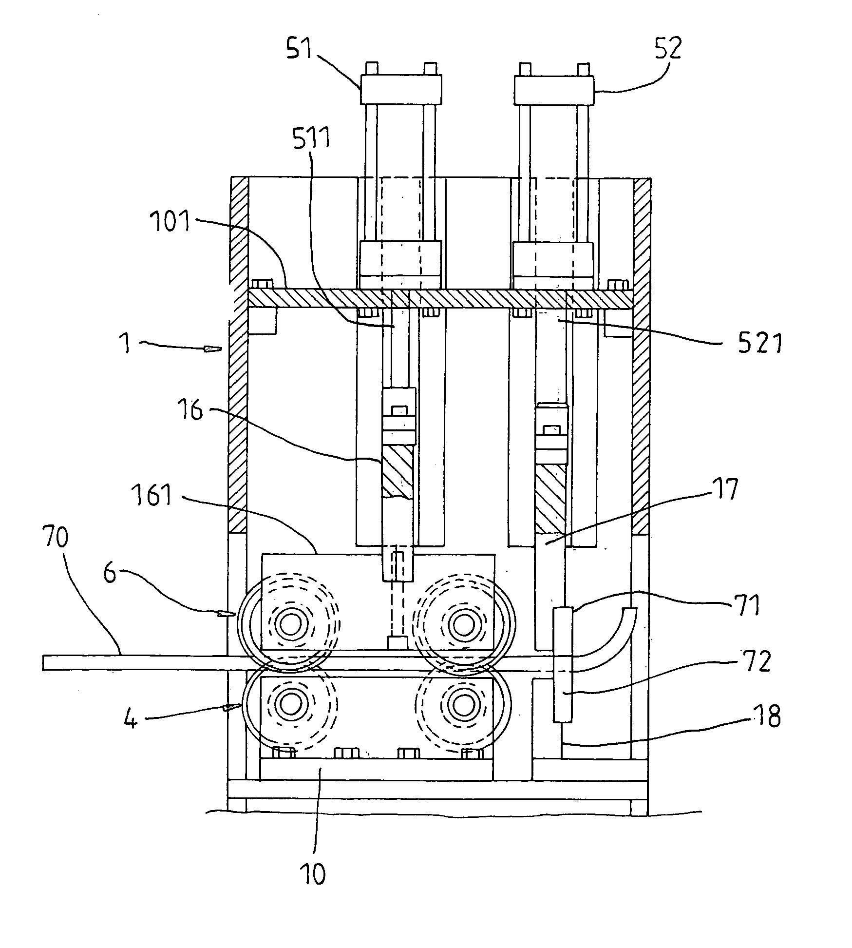
[0015]Referring to FIGS. 3-9, a corrugated sheet member bending machine in accordance with the present invention is shown comprising a base frame 2, two upright supports 21 symmetrically disposed at front and rear sides of the base frame 2, two sliding racks 312 and 322 arranged in parallel on the top wall of the base frame 2 near the front and rear sides of the base frame 2, a housing 1 pivotally supported on the upright supports 21 by a pivot shaft 11, two gears 12 fixedly provided at the front and sides of the housing 1 and respectively meshed with the sliding racks 312 and 322 (see FIG. 4), and two hydraulic cylinders 31 and 32 respectively mounted on the top wall of the base frame 2 and coupled with the respective piston rods 311 and 321 to the sliding racks 312 and 322. By means of operating the hydraulic cylinders 31 and 32 to extend out the respective piston rods 311 and 321, the sliding racks 312 and 322 are moved to rotate the gears 12, and therefore the housing 1 is turne...


PUM


Abstract

A corrugated sheet member bending machine is disclosed to include a base frame, a housing pivotally supported on the base frame and turnable within 90-degrees to fit different workpiece insertion angles and different workpieces, a set of drive rollers mounted on a wheel shaft and rotatable by a motor, a set of driven rollers pivotally supported on a sliding plate movable relative to the drive rollers by a hydraulic cylinder, a bottom die fixedly mounted inside the housing at the bottom, and a movable upper die movable by a hydraulic cylinder for stamping on the inserted workpiece against the bottom die to curve the workpiece.

Description

BACKGROUND AND SUMMARY OF THE INVENTION[0001]The present invention relates to a corrugated sheet member bending machine and more particularly, to a simple structure of corrugated sheet member bending machine, which saves much installation space and fits different workpiece insertion angles.[0002]Regular corrugated sheet members are made in a flat shape for covering the flat roof of a building. When encountered a curved area on the roof, a plastic sheet member may be used to join two flat type corrugated sheet members and to cover the curved area of the roof. However, the use of a plastic sheet member to join two corrugated sheet members obstructs the total sense of beauty. In order to eliminate this drawback, a corrugated sheet member bending machine is developed and used to bend a corrugated sheet member subject to the desired shape. FIGS. 1 and 2 show a corrugated sheet member bending machine according to the prior art. This design of corrugated sheet member bending machine is sti...

Claims


Application Information

Patent Timeline
IPC IPC(8): B21D5/01B21D5/14
CPCB21D5/08
Inventor CHUANG, SEN-JUNG
Owner CHUANG SEN JUNG
Why Eureka
Try Eureka