
Support for electrical/electronic structure and/or electrical power supply structure for a hand dynamometer tool, in particular for a torque wrench operating by breaking mechanical equilibrium

a technology of electrical/electronic structure and electrical power supply structure, which is applied in the direction of force/torque/work measurement apparatus, manufacturing tools, instruments, etc., can solve the problems of affecting the overall compactness

Inactive Publication Date: 2008-01-01
STANLEY BLACK & DECKER MEA FZE
View PDF22 Cites 5 Cited by
  • Summary
  • Abstract
  • Description
  • Claims
  • Application Information

AI Technical Summary

Benefits of technology

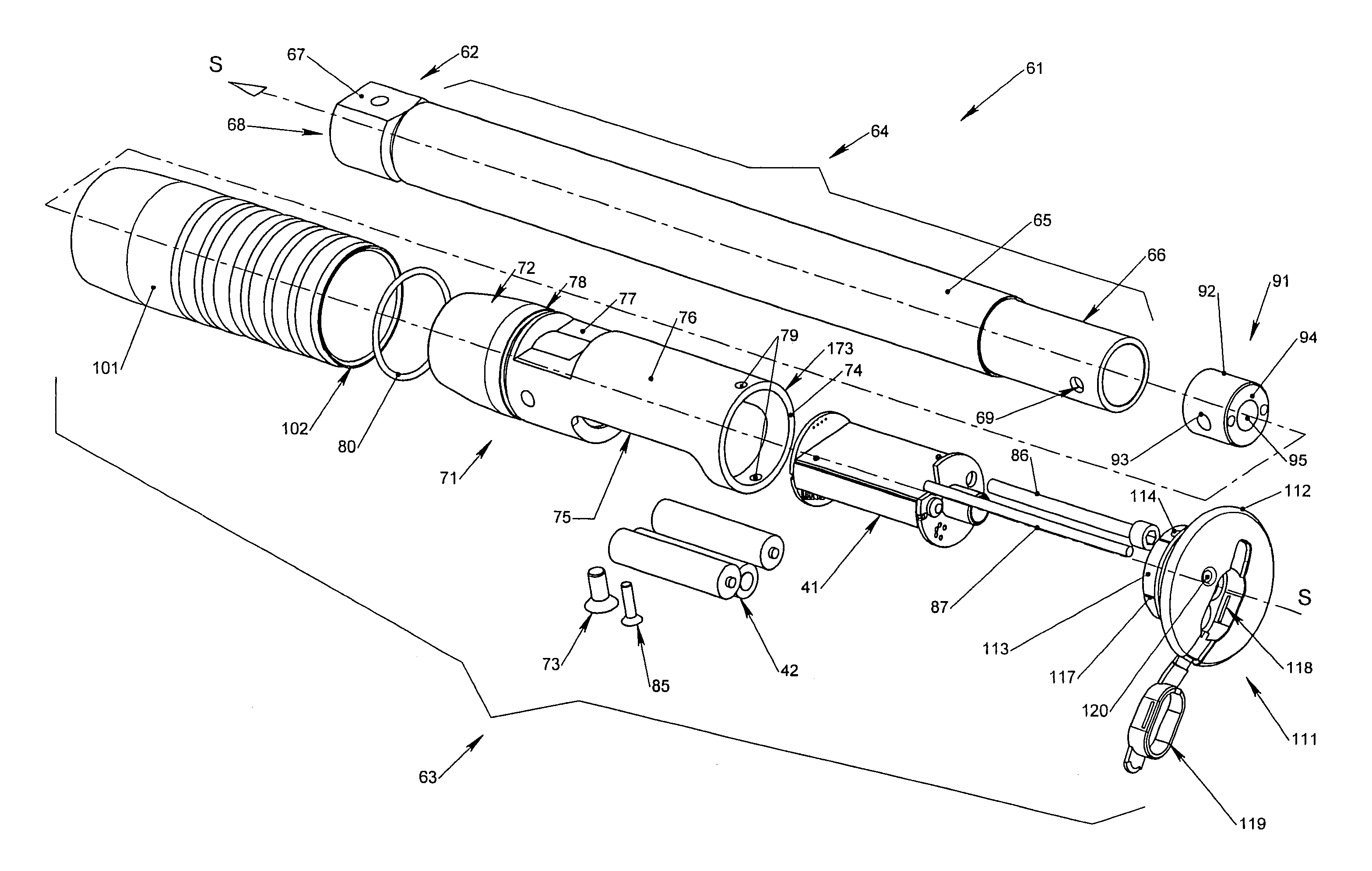
"The invention provides a support for a hand dynamometer tool that can support electrical and electronic structures, as well as a power supply and measurement structures. The support is a cylindrical body with recesses and seats for receiving power supply members and circuit boards. The support also has positioning and fastening structures for positioning and fastening electrical / electronic elements perpendicular to the support. The tool also includes an equilibrium-breaking mechanism, a calibration device, and a data management and transmission structure. The support module is a one-piece part made of plastic material and includes a support, at least one battery, and at least one circuit board. The tool also includes the support module entirely inside the tool. The technical effects of the invention include improved functionality and accuracy of the hand dynamometer tool."

Problems solved by technology

Such positioning suffers from a drawback of occupying a very large volume, which is detrimental to overall compactness.
In addition, access to other internal assemblies of the tool requires partial disassembly and complete removal of electrical power supply sources.

Method used


Image

  • Support for electrical/electronic structure and/or electrical power supply structure for a hand dynamometer tool, in particular for a torque wrench operating by breaking mechanical equilibrium
  • Support for electrical/electronic structure and/or electrical power supply structure for a hand dynamometer tool, in particular for a torque wrench operating by breaking mechanical equilibrium
  • Support for electrical/electronic structure and/or electrical power supply structure for a hand dynamometer tool, in particular for a torque wrench operating by breaking mechanical equilibrium

Examples


Embodiment Construction

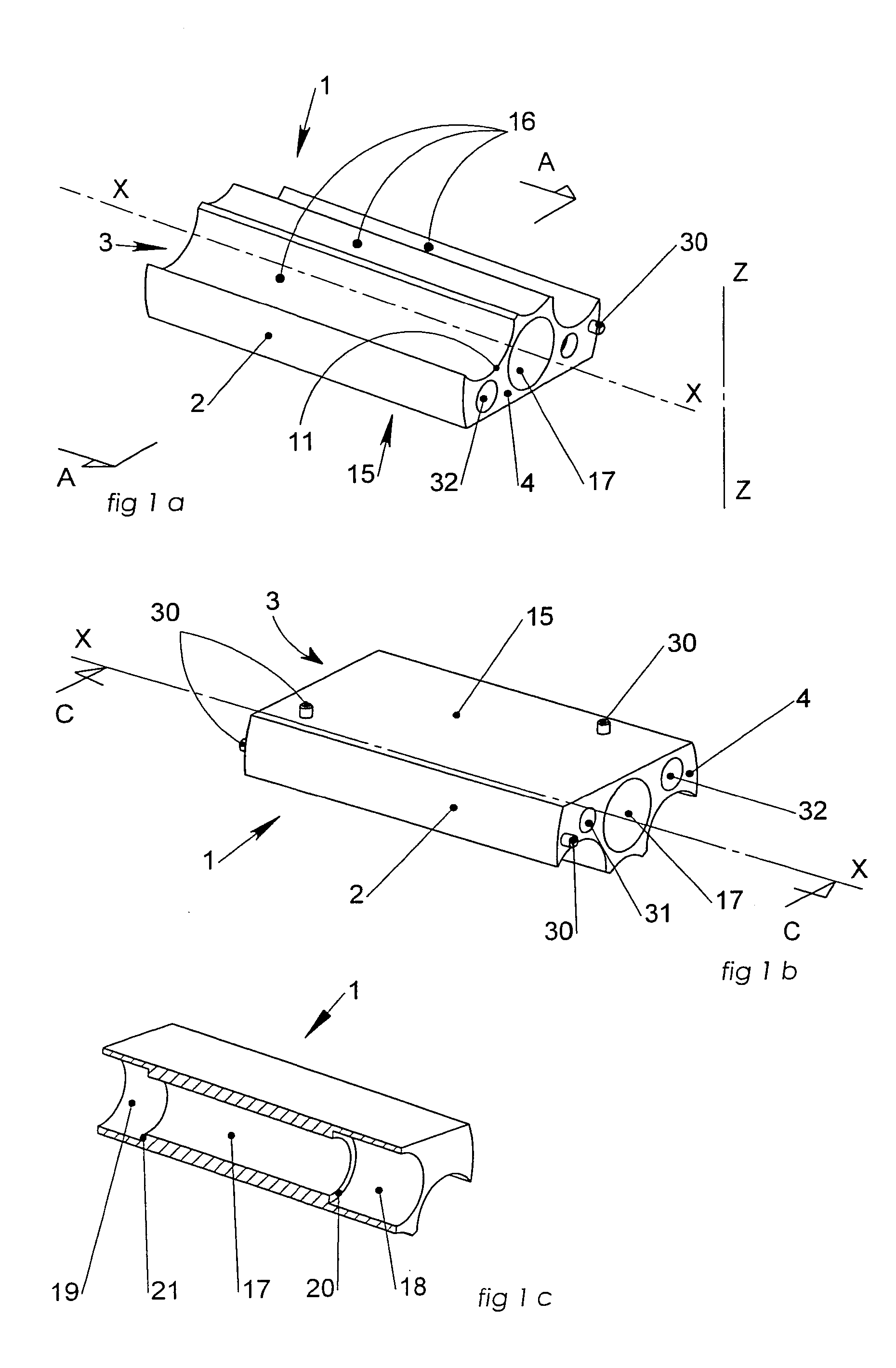
[0036]A support shown in perspective in FIGS. 1a and 1b is adapted to receive electrical / electronic structure and / or electrical power supply structure for a hand dynamometer tool.

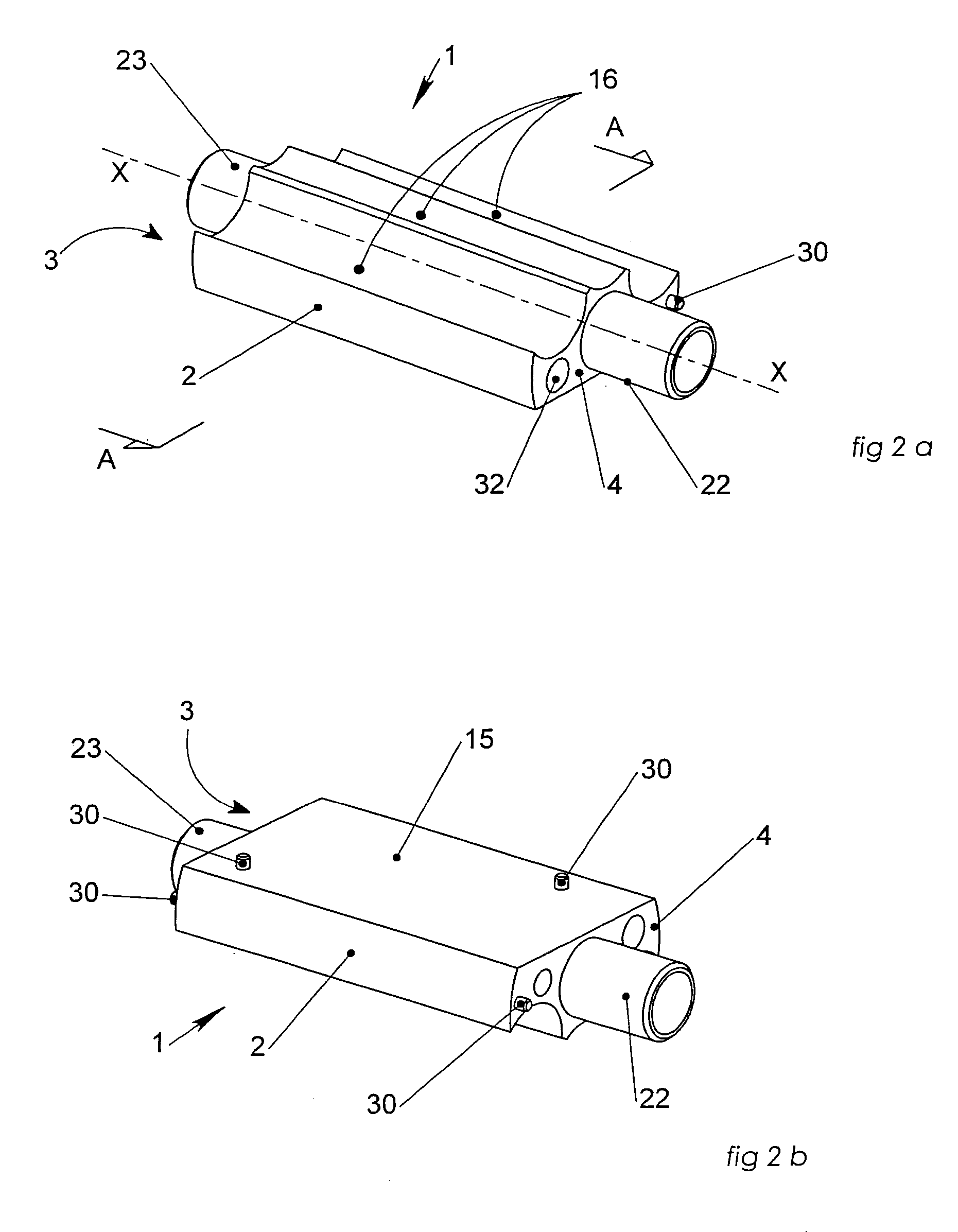
[0037]Support 1 has a body 2 that is substantially cylindrical in shape and that extends along an axis X-X. The support 1 is defined axially by a first end face 3 and by a second end face 4, which end faces are substantially perpendicular to the axis X-X.

[0038]The body 2 is provided externally with a planar surface 15 parallel to the axis X-X forming a seat suitable for receiving an electronic circuit board, and with three cylindrical recesses 16 extending longitudinally along axes parallel to the axis X-X of the support 1, and suitable for receiving electrical power supply structure such as optionally rechargeable batteries of the “AAA” type.

[0039]The recesses and / or seats are distributed about the axis X-X, at a periphery of the body 2, radially and facing outwardly relative to a longitudinal axis of the ...


PUM


Abstract

A support is for supporting electrical and / or electronic structure and / or electrical power supply structure for a hand dynamometer tool, in particular for a torque wrench operating by breaking mechanical equilibrium. A body of a substantially cylindrical shape that extends along a longitudinal axis, defined by two end faces, recesses and / or seats suitable for receiving electrical power supply members and / or electrical / electronic circuit boards are arranged and distributed around the axis, on or close to a periphery of the support. The support can be applied to a support module for a hand dynamometer tool and to a dynamometer tool.

Description

[0001]The present invention relates to a support for supporting electrical and / or electronic structure and / or electrical power supply structure for a hand dynamometer tool, in particular for a torque wrench operating by breaking mechanical equilibrium.BACKGROUND OF THE INVENTION[0002]It is known that electrical / electronic and / or electrical power supply structure for a dynamometer tool comprise electrical / electronic circuits and components that are powered by batteries.[0003]Such structure is generally positioned flat, side-by-side, inside the tool or else projecting from outside of the tool.[0004]Such positioning suffers from a drawback of occupying a very large volume, which is detrimental to overall compactness.[0005]In addition, access to other internal assemblies of the tool requires partial disassembly and complete removal of electrical power supply sources.[0006]In this context, the present invention mitigates drawbacks of the prior art by proposing a support for electrical / el...

Claims


Application Information

Patent Timeline
Patent Type & Authority Patents(United States)
IPC IPC(8): B25B23/14B25B23/147B25B23/159B25B23/142
CPCB25B23/1425
Inventor CUPIF, BERTRANDPRAUDEL, PHILIPPEVECCHIO, JOCELYN
Owner STANLEY BLACK & DECKER MEA FZE
Learn More