

Retroreflection sheeting and film for use in retroreflection sheeting
a technology of retroreflection and film, applied in the direction of optics, thin material processing, instruments, etc., can solve the problems of inability to segregate recycling, inability to incinerate, and inability to acquire sufficient retroreflection, and achieve superior incident angularities and direction characteristics. superior
Inactive Publication Date: 2008-01-01
KANEKA CORP
View PDF22 Cites 7 Cited by
- Summary
- Abstract
- Description
- Claims
- Application Information
AI Technical Summary
Benefits of technology
The present invention provides a retroreflective sheeting with triangular pyramidal frustum prism elements that exhibit proper retroreflection even at small incident angles with no or minimal halation. The sheeting has superior incident angularities and direction characteristics. The invention also provides a resin film for use in the retroreflective sheeting. The technical effects of the invention include improved retroreflective performance, reduced halation, and improved directionality.
Problems solved by technology
However, in the above arrangement, the absolute value of a luminance factor (i.e. a coefficient of retroreflection) is small, which obstructs acquiring sufficient retroreflection.
In addition to the above drawback, since segregation of the glass beads from the resin is impossible, segregation recycling is impossible, and incineration is impossible.
However, the incident angularities are poor.
Accordingly, in practical use of the retroreflective sheeting above, in the case where light emitted from a headlamp of an automobile is retroreflected on a traffic signboard, for instance, the retroreflected light may be hard to reach the driver's eyes if the driver is located on an off-axis position of the optical axis of the retroreflected light due to the narrow diffuse angle of the retroreflected light.
The method in the publication above, however, has no specific disclosure about a microsized triangular pyramid type reflective element, and has no recitation on a desirable size and a desirable optical axis tilt of the triangular pyramid type reflective element.
However, the improvement is insufficient, and in the case where the coefficient of retroreflection when both the incident angle and the observation angle are small is exceedingly large, halation which makes the recognition of a sign or the like difficult for a driver may likely occur due to too bright reflected light; whereby the driver may be misguided.
On the other hand, in the case of where the retroreflection is to be improved when the incident angle is larger, the retroreflective performance (i.e. the coefficient of retroreflection) may be degraded when both the incident angle and the observation angle are small, which may fail to provide sufficiently enhanced incident angularities.
Also, an attention should be paid in attaching a retroreflective sheeting on a base member in view of a drawback that the retroreflective performance is extremely varied between vertical direction and horizontal direction, in other words, direction characteristics are poor.
So far, there is no specific technical disclosure to solve the drawback.
However, the reflective element layer having the protruding supports in the firm contact with the backing sheet cannot meet the total internal reflection requirement.
Moreover, since according to the retroreflective sheetings produced by the aforementioned methods, the triangular pyramidal element has a very sharp apex, in attaching the backing sheet, the sharp apex may be abraded or deformed, which cause undesirable fluctuation of the retroreflective performance, and further, when the retroreflective sheeting is temporarily rolled in after the prism elements are formed, the triangular pyramidal elements may be abraded in the roll, and consequently broken.
Since the portion containing the broken prism elements is unusable as a product, and should be disposed of, environmental load may be increased.
Method used
View moreImage
Smart ImageViewing Examples

Examples
examples
[0084]In the following, the invention will be described in further details by illustrating examples and comparative examples, which, however, do not delimit the invention.
Login to View More PUM
| Property | Measurement | Unit |
|---|---|---|
| side length | aaaaa | aaaaa |
| side length | aaaaa | aaaaa |
| length | aaaaa | aaaaa |
Abstract
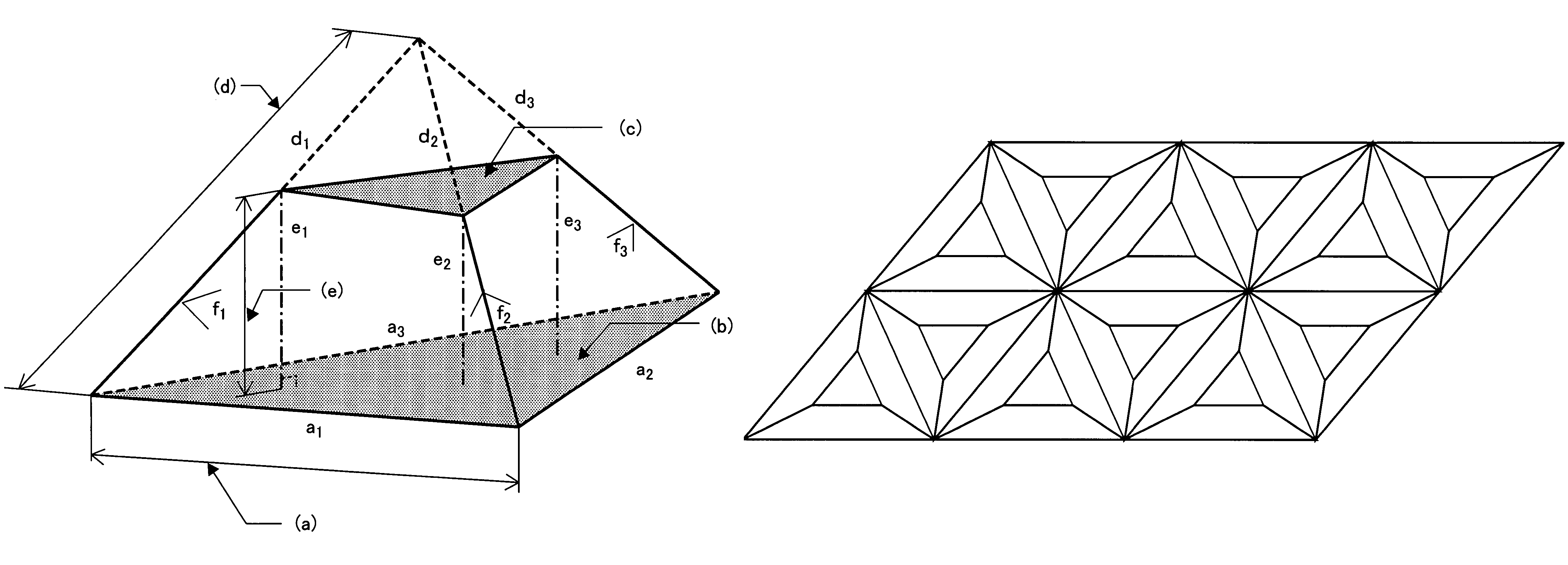
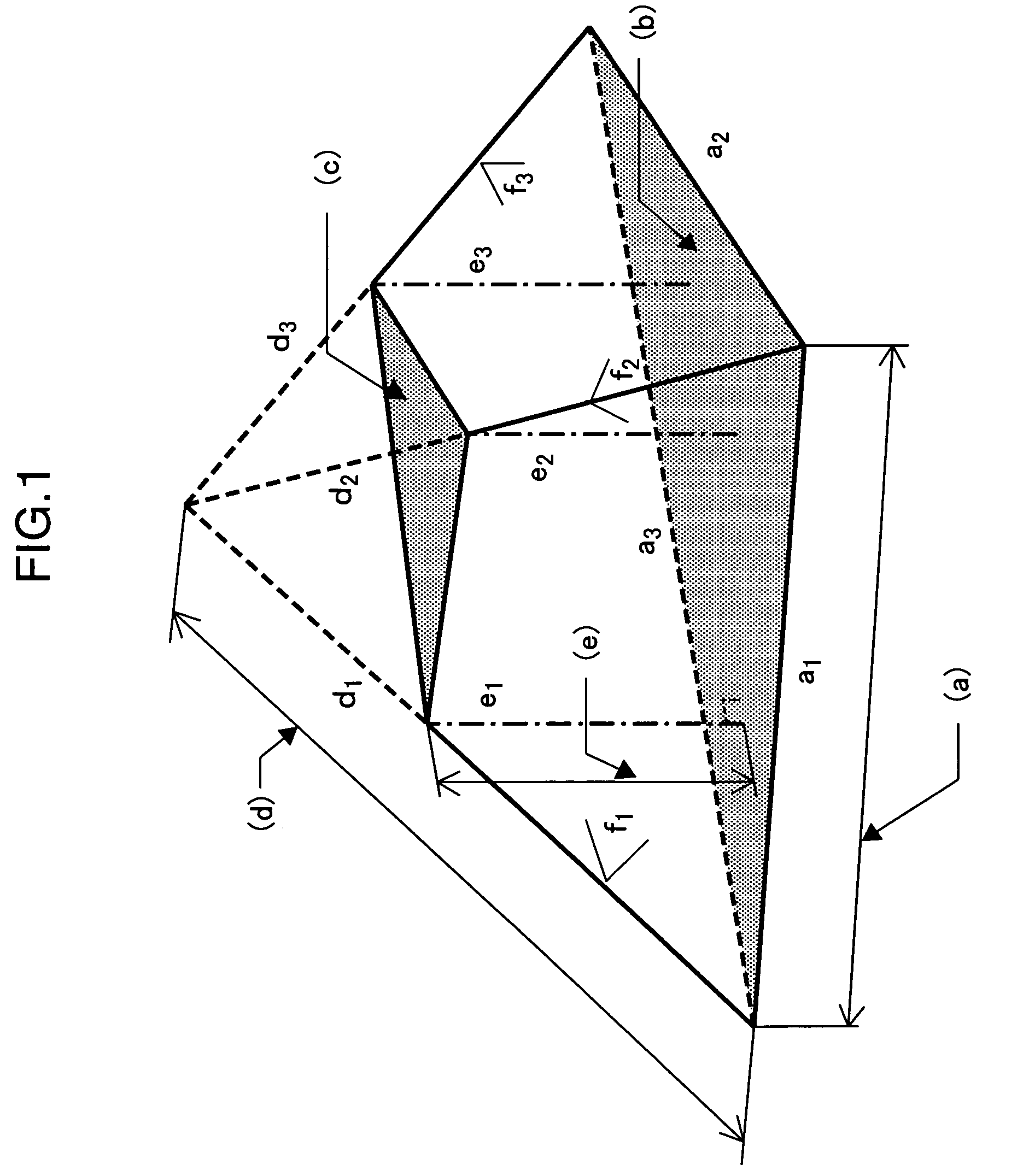
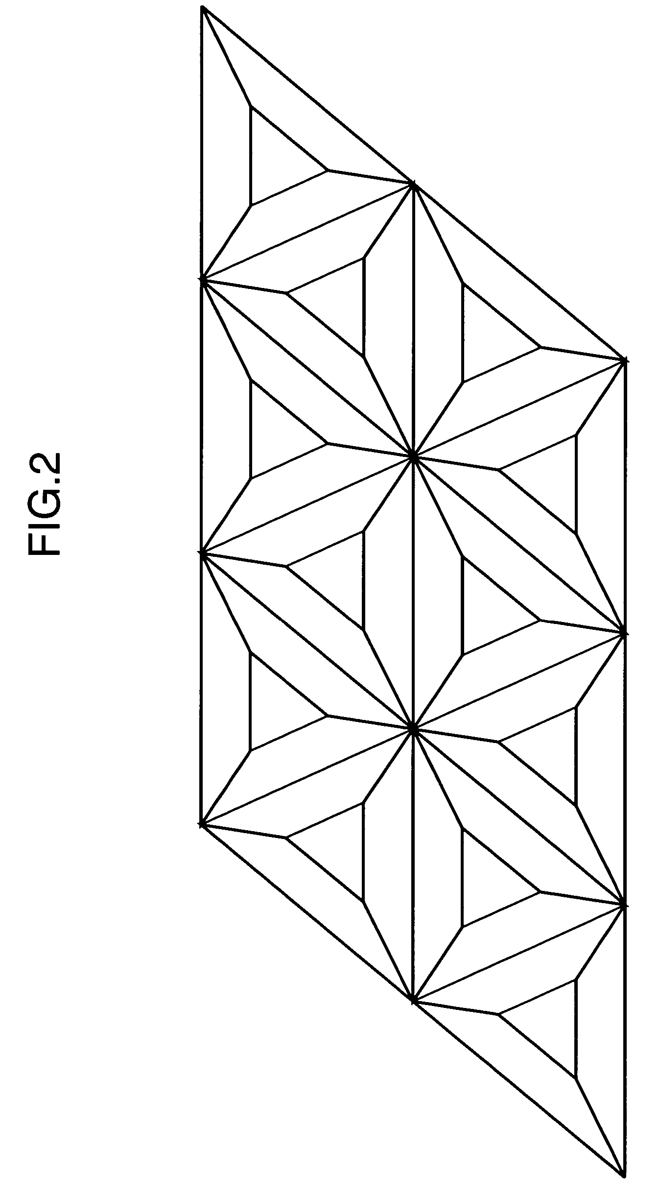
An object of the present invention is to provide a retroreflective sheeting that exhibits proper retroreflection even at a small incident angle with no or less halation, and has superior incident angularities and superior direction characteristics, as well as a film for use in the retroreflective sheeting. The retroreflective sheeting with the above characteristics is obtained by forming reflective elements of a specific triangular pyramidal frustum configuration in a close-packed state on one surface thereof. The shape of the triangular pyramid frustum element satisfies following requirements: one side length of the bottom surface is in the range of 50 to 400 μm, and a difference between a longest side and a shortest side is 200 μm or less; the length of a longest edge is in the range of 50 to 400 μm, and a difference between the longest edge and a shortest edge among the three edges is 100 μm or less; when a vertical line which intersects perpendicularly with the bottom surface is drawn from a top surface to the bottom surface, the length of a longest vertical line is in the range of 20 to 250 μm; and an angle between adjacent side surfaces is in the range of 85 to 95 degrees.
Description
TECHNICAL FIELD[0001]The present invention relates to a retroreflective sheeting with prism elements of a novel structure. More specifically, the invention relates to a retroreflective sheeting comprising a reflective element layer containing triangular pyramidal frustum prism elements of a novel structure, as well as a resin film for use in the retroreflective sheeting.BACKGROUND ART[0002]The retroreflective sheeting is used for signboards such as road signboards and construction site signboards, car license plates of automotive vehicles such as automobiles and motorcycles, and safety materials such as collision warning signboards, clothing, and life jackets.[0003]There are proposed some techniques of obtaining retroreflection by embedding micro glass beads in a resin sheet and utilizing refraction of the glass beads (see Japanese Unexamined Patent Publication No. 6-160615, Japanese Unexamined Patent Publication No. 6-347623, and Japanese Unexamined Patent Publication No. 9-212115)...
Claims
Login to View More Application Information
Patent Timeline
 Patent Type & AuthorityPatents(United States)
IPC IPC(8): G02B5/124
CPCG02B5/124Y10T428/254
InventorKOIZUMI, KEISHINAKATANI, KAZUSHI
OwnerKANEKA CORP