Coaxial cable jumper device

a technology of coaxial cables and jumpers, which is applied in the direction of coaxial cables/analogue cables, coaxial cable connections, cables, etc., can solve the problems of insufficient resistance of cables to pull forces, inability to meet the needs of outdoor environment, so as to facilitate passage through space, minimize thickness build-up, and provide stability of electrical characteristics during flexure

Active Publication Date: 2008-01-01
TIMES FIBER COMMUNICATIONS INC
View PDF16 Cites 36 Cited by
  • Summary
  • Abstract
  • Description
  • Claims
  • Application Information

AI Technical Summary

Benefits of technology

[0007]The present invention relates to a coaxial cable that has a flat portion, so that the cable can be used, for example, as a jumper cable that passes through a window sill, a door jam or under a rug. Because the cable is flat, it can easily pass through a space in the door jam or window sill without requiring holes to be drilled into the building structure or in any application where a flat cable jumper may be advantageous to the installed environment. In addition, through its design, the cable provides the electrical performance, the mechanical pull strength and environmental and electromagnetic isolation not available in current state-of-the-art products.
[0008]In one embodiment, a central conductor is surrounded by a substantially flat dielectric, an inner laminate tape, a outer metal tape conductor, or an outer conductor consisting of braided, woven or wrapped metallic wires and an outer covering. The inner laminate tape with its bonding layer immediately adjacent to the dielectric core is folded over the underlying dielectric core in a manner to minimize thickness build-up and is preferably heat sealed to the dielectric core. The central conductor of the dielectric core is soldered, or otherwise electrically bonded or attached, to the central conductor of the end connectors. The transition area, where the conductor is attached to the end connector, is then covered with a dielectric shrink tube or wrapped with a dielectric tape material, such as polytetrafluoroethylene (PTFE) or polyethylene (PE). The diameter of the transition area should be approximately the same thickness as the dielectric core. The laminate tape is then electrically bonded to an integral or machined solderable ring part of the end connector to provide stability of the electrical characteristics during flexure. The outer metal tape conductor is sealed along its edges both radially and longitudinally. Each end of the cable preferably has a end connector that includes an integral solderable metallic ring or a separate machined, solderable, metallic ring. The outer metal tape conductor may then be soldered and sealed to the solderable ring. This soldering and sealing of the outer metal tape to the integral or machined metallic ring provides the mechanical pull strength and environmental and electromagnetic isolation not available in current state-of-the-art products.
[0009]An adhesive or bonding material may be applied over the outer metal tape to bond the core to the outer jacket to improve the flexure performance of the jumper. A heat shrink tube may then be applied over the outer metal tape including the solderable ring. The heat shrink tubing may be, but is not limited to, PE, polyvinylchloride (PVC), polyvinylidene fluoride (PVDF), polyurethane (PU), PTFE, or other heat shrinkable or extrudeable jacket materials. Crimpable clamps may be used to further secure the jacket material to the core. On the outer jacket, an adhesive agent may be applied to allow for adhesion to surfaces where such an attribute is advantageous to the installation environment.
[0010]In another embodiment of the invention, the cable includes an alternate type connector (“F”, BNC, RCA, etc.) on at least one end of the cable and a direct connection to a device on the other end of the cable. The alternate type connector may be male or female and the cable may be flat for its entire length or flat for only a portion of its length with the remainder being round with a braided or other type of outer conductor that provides increased flexibility.
[0013]In another embodiment, the cable includes connectors on each end such that the cable connects directly to both devices but only the portion of the cable that passes under the window sill or door jam is flat and the rest of the cable is substantially round, with a braided, served or other type of outer conductor that provides increased flexibility.

Problems solved by technology

Moreover, currently available coaxial cables may, in some cases, have deficiencies that limit their usefulness in the outdoor environment.
For example, some cables will not sufficiently resist pulling forces and therefore may come apart when pulling forces are applied.
Some cables also allow moisture to enter at one end and cause damage to the cable.
Additionally, the inventor has found that existing cables often do not provide sufficient electrical performance as well as electromagnetic and / or environmental isolation from the outside.

Method used


Image

  • Coaxial cable jumper device
  • Coaxial cable jumper device
  • Coaxial cable jumper device

Examples


Embodiment Construction

[0021]This disclosure provides and discloses exemplary embodiments. In particular, the specification discloses one or more embodiments that incorporate the features of the invention. The embodiment(s) described, and references in the specification to “one embodiment”, “an embodiment”, “an example embodiment”, etc., indicate that the embodiment(s) described may include a particular feature, structure, or characteristic, but every embodiment may not necessarily include the particular feature, structure, or characteristic. Moreover, such phrases are not necessarily referring to the same embodiment. Further, when a particular feature, structure, or characteristic is described in connection with an embodiment, persons skilled in the art may effect such feature, structure, or characteristic in connection with other embodiments whether or not explicitly described.

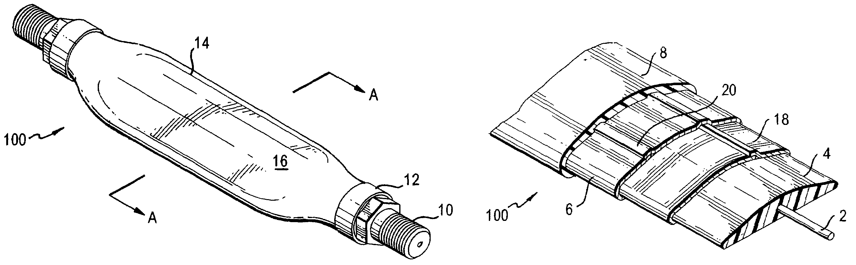
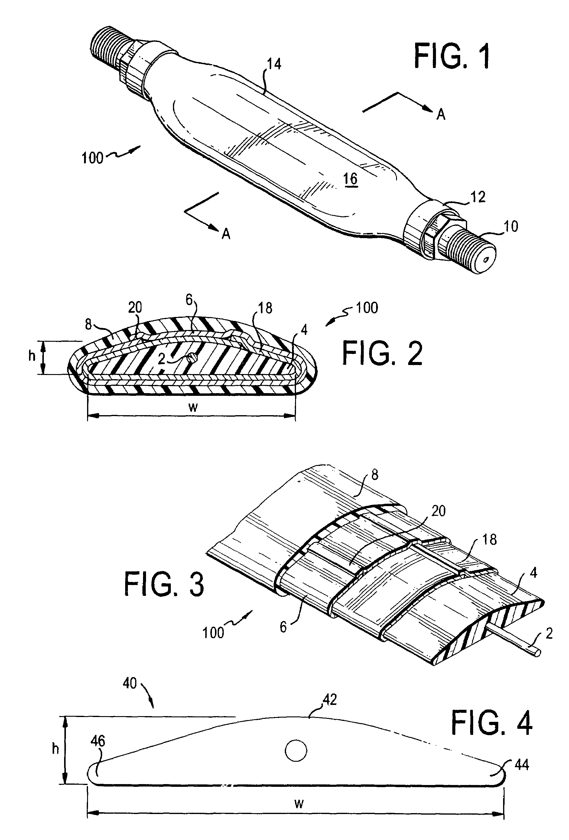
[0022]FIG. 1 shows an embodiment of the present invention. The cable (100) generally contains two ends and a middle portion (16)...


PUM


Abstract

The present invention relates to a coaxial cable having a flat portion, so that the cable can be used, for example, as a jumper cable that passes through a window sill or a door. Because the cable is flat, it can easily pass through a crack in the door or window without requiring holes to be dilled into the building structure. The flat portion of the cable contains a central conductor that is sequentially surrounded by a substantially flat dielectric, an outer conductor, and a jacket.

Description

FIELD OF THE INVENTION[0001]The present invention is generally related to coaxial cables and, in particular to coaxial cables with a flattened portion.BACKGROUND OF THE INVENTION[0002]Coaxial cables have long been used to provide a junction between electrical devices. Coaxial cables are usually composed of an elongated central conductor of metal containing a concentrically situated elongated outer tubular conductor of metal, both conductors being separated by a layer of an electrically insulating material. The central conductor may be composed of a single wire or multiple strands of wires.[0003]Coaxial cables are used in many areas such as transmission and computer cables, computer networking, video signal transmission, instrumentation cables, broadcast cables, e.g. TV companies between the community antenna and user homes or businesses, telephone companies, medical e.g. ultrasound devices, and lightweight coaxial cables for satellites. For some of these applications, connection of ...

Claims


Application Information

Patent Timeline
Patent Type & Authority Patents(United States)
IPC IPC(8): H01R4/00H01R24/38
CPCH01B11/1895H01R24/542H01R4/023H01R2103/00H01R13/622H01B11/18
Inventor AMATO, ALAN JOHNMERCADO, JESUSCOOKE, TIMOTHY D.CARROLL, LARRY
Owner TIMES FIBER COMMUNICATIONS INC
Why Eureka
Try Eureka