Superconducting rotating machines with stationary field coils

a superconducting rotating machine and stationary field technology, applied in the direction of windings, magnetic circuit rotating parts, magnetic circuit shape/form/construction, etc., can solve the problems of degrading affecting the performance of the superconductor, and difficult design, fabricating and operating such a rotor, so as to improve the performance characteristics and increase the torque density

Inactive Publication Date: 2008-01-01
GENERAL ELECTRIC CO
View PDF18 Cites 33 Cited by
  • Summary
  • Abstract
  • Description
  • Claims
  • Application Information

AI Technical Summary

Problems solved by technology

Accordingly, designing, fabricating and operating such a rotor may be difficult.
Specifically, because the coils are coupled to the rotor, the coils may be subjected to centrifugal forces that may cause strains and degrade the performance of the superconductor.

Method used


Image

  • Superconducting rotating machines with stationary field coils
  • Superconducting rotating machines with stationary field coils
  • Superconducting rotating machines with stationary field coils

Examples


Embodiment Construction

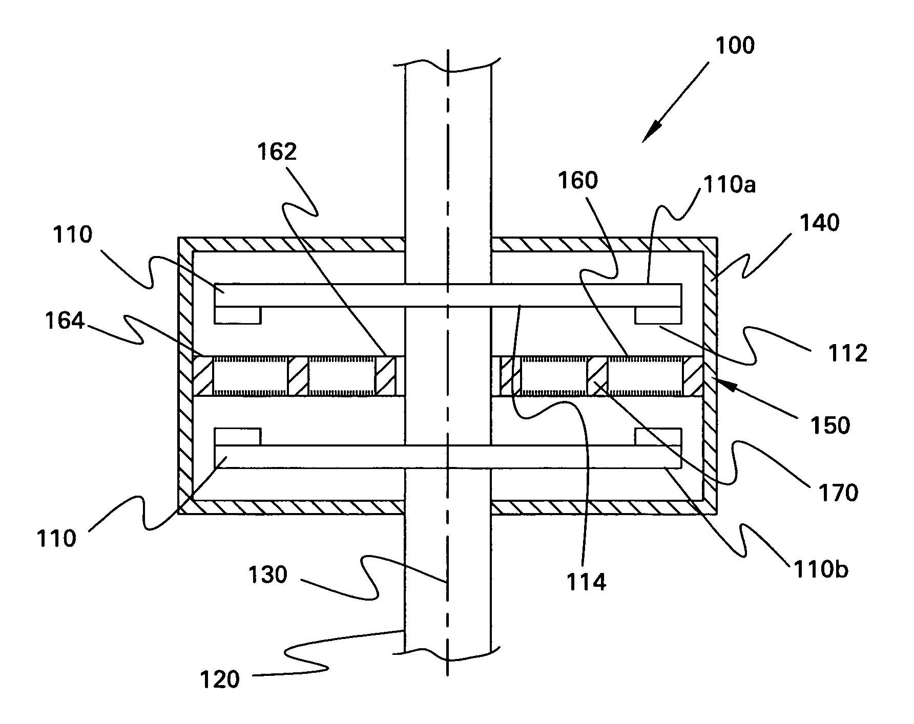
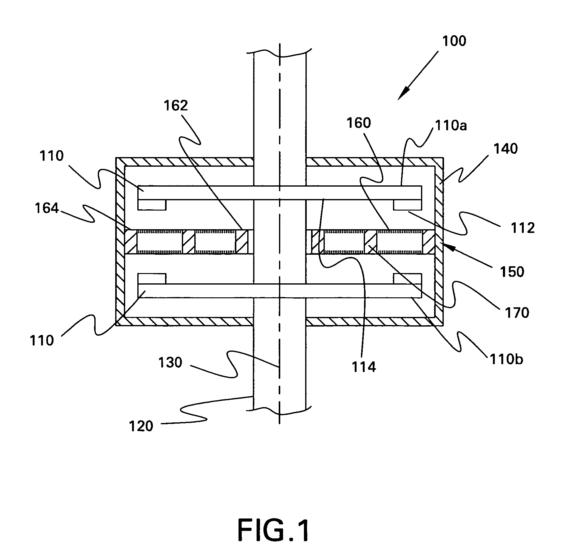
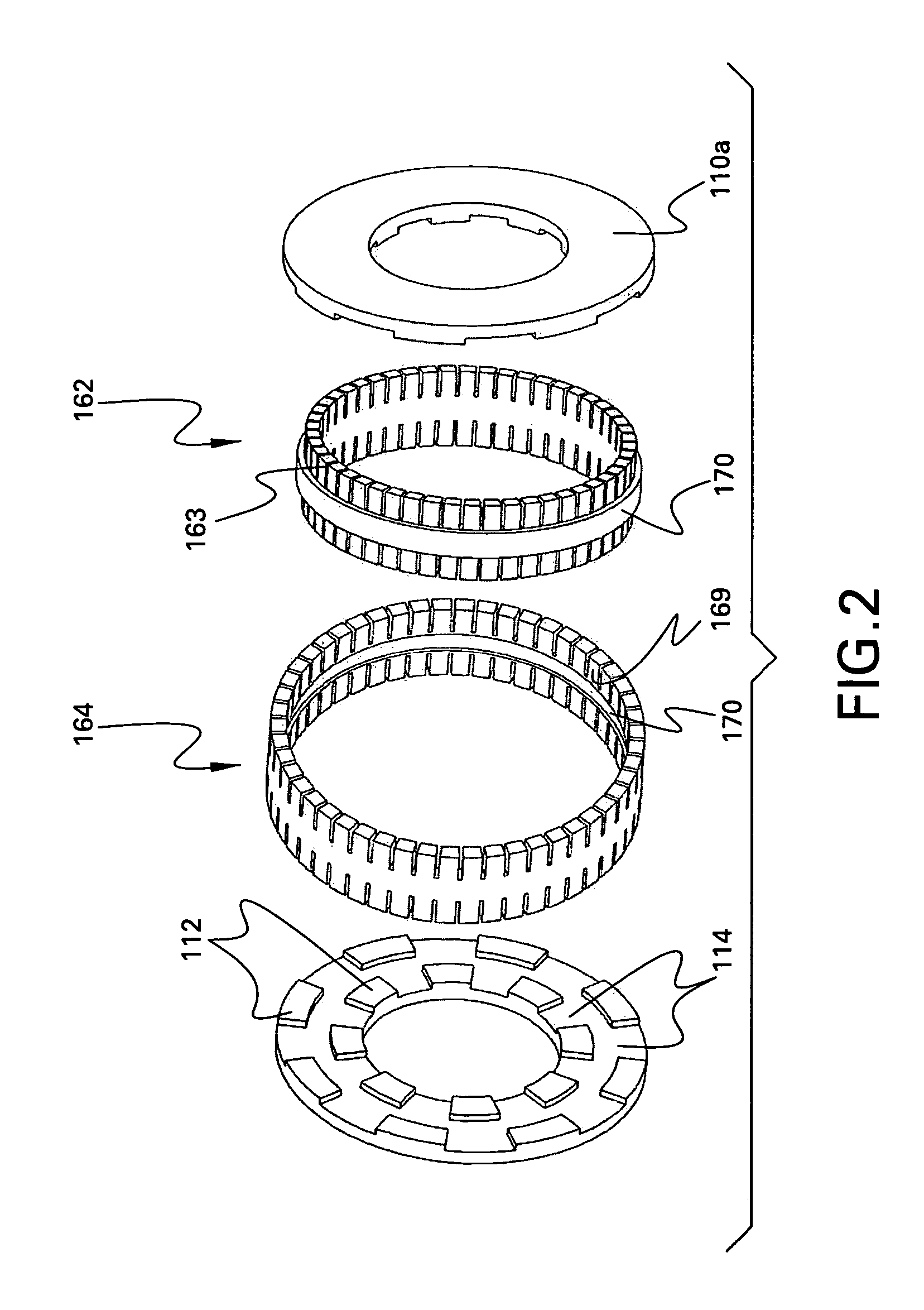
[0017]FIG. 1 is a cross-sectional view of an exemplary embodiment of an electrical machine 100. The machine 100 may operate as a motor and / or as a generator as desired. The machine 100 includes a rotor assembly 110 having a pair of rotor segments 110a, 110b mounted on a shaft 120. The shaft 120 is preferably formed of a non-ferromagnetic material, such as stainless steel. The rotor segments 110a, 110b are adapted to rotate as the shaft rotates about its longitudinal axis 130 and are spaced-apart axially along the shaft 120. Each rotor segment 110a, 110b includes a plurality of salient poles, such as iron poles 112 and a plurality of air poles 114. Embodiments of the rotor assembly 110 and rotor segments are described in detail below with reference to FIGS. 4 and 5.

[0018]The rotor assembly 110 is substantially enclosed within a stationary housing 140. The housing 140 rotatably supports the rotor assembly 110. The housing 140 is of a substantially cylindrical configuration. A stator a...


PUM


Abstract

A machine includes a rotatable rotor assembly having a number of salient poles. The machine further includes a stationary stator assembly having concentric inner and outer stators, at least one stationary superconducting field coil and at least one stator coil. The stationary superconducting field coil is disposed between the inner and outer stators and is mounted on at least one of the inner and outer stators. The stationary superconducting field coil and the salient poles are configured relative to each other, such that when the rotor assembly is rotated relative to the stator assembly around a predetermined axis, a rotating magnetic field is produced with an airgap flux direction substantially along the predetermined axis. The interaction between the stationary superconducting field coil and the rotating poles provides the only source of a time varying magnetic flux supplied to the stator coil.

Description

CROSS REFERENCE TO RELATED APPLICATIONS[0001]This application is a continuation in part of U.S. patent application, Ser. No. 10 / 792,503 filed Mar. 3, 2004 now U.S. Pat. No. 7,049,724, entitled “Superconducting Rotating Machines with Stationary Field Coils and Axial Airgap Flux,” which is incorporated herein by reference in its entirety.BACKGROUND OF THE INVENTION[0002]The present invention relates generally to electrical motor / generators, and more particularly to machines including superconducting windings.[0003]At least some known superconducting electric machines include a superconducting field coil installed on the rotor. The superconducting coil is maintained at a temperature approaching zero degrees Kelvin using a continuous supply of cryogenic fluid, such as, for example, but not limited to liquid helium (He2). If a high temperature superconductor (HTS) is used in fabricating the field coil, a cryogenic fluid such as nitrogen (N2) may be used to achieve superconducting tempera...

Claims


Application Information

Patent Timeline
Patent Type & Authority Patents(United States)
IPC IPC(8): H02K1/00H02K31/00H02K1/22H02K3/00
CPCH02K3/28H02K19/20H02K55/06Y02E40/627Y02E40/60
Inventor QU, RONGHAIBRAY, JAMES WILLIAM
Owner GENERAL ELECTRIC CO
Why Eureka
Try Eureka