Voltage regulator

a voltage regulator and output short circuit technology, applied in the direction of electric variable regulation, process and machine control, instruments, etc., can solve the problem of difficult control of output short circuit current to a set valu

Active Publication Date: 2008-01-01
ABLIC INC
View PDF6 Cites 13 Cited by
  • Summary
  • Abstract
  • Description
  • Claims
  • Application Information

AI Technical Summary

Benefits of technology

[0014]According to the voltage regulator of the present invention, the current limiting circuit for controlling the output short circuit current to a set value is provided, whereby there is offered an effect that the dispersion in the output short circuit current due to the manufacturing dispersion can be eliminated. Moreover, the output short circuit current controlled by the current limiting circuit can be set to a desired value.

Problems solved by technology

Hence, there arises a problem in that dispersion is generated in an output short circuit current due to an influence of the manufacturing dispersion in the threshold voltage of the N-channel MOS transistor 23 and the resistance value of the resistor 22, and thus it is difficult to control the output short circuit current to a set value.

Method used


Image

  • Voltage regulator
  • Voltage regulator
  • Voltage regulator

Examples


Embodiment Construction

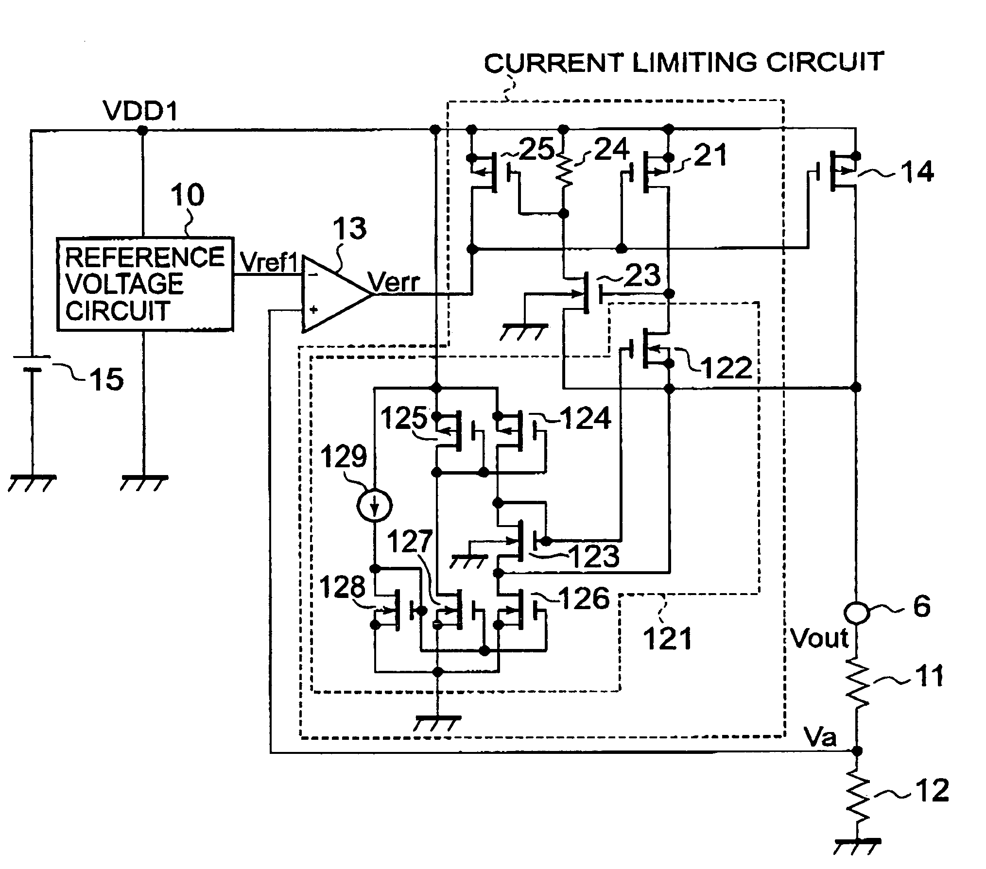
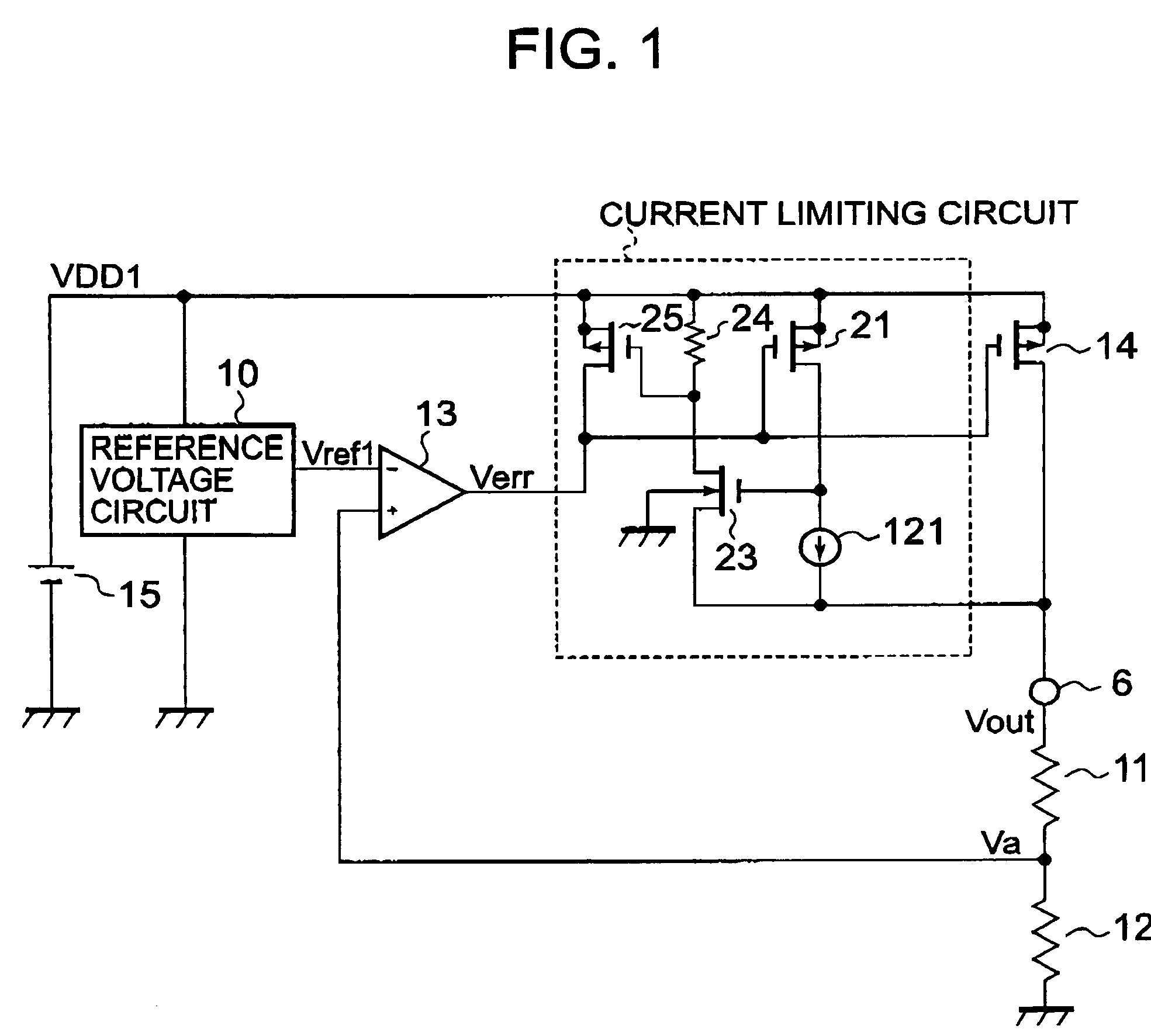
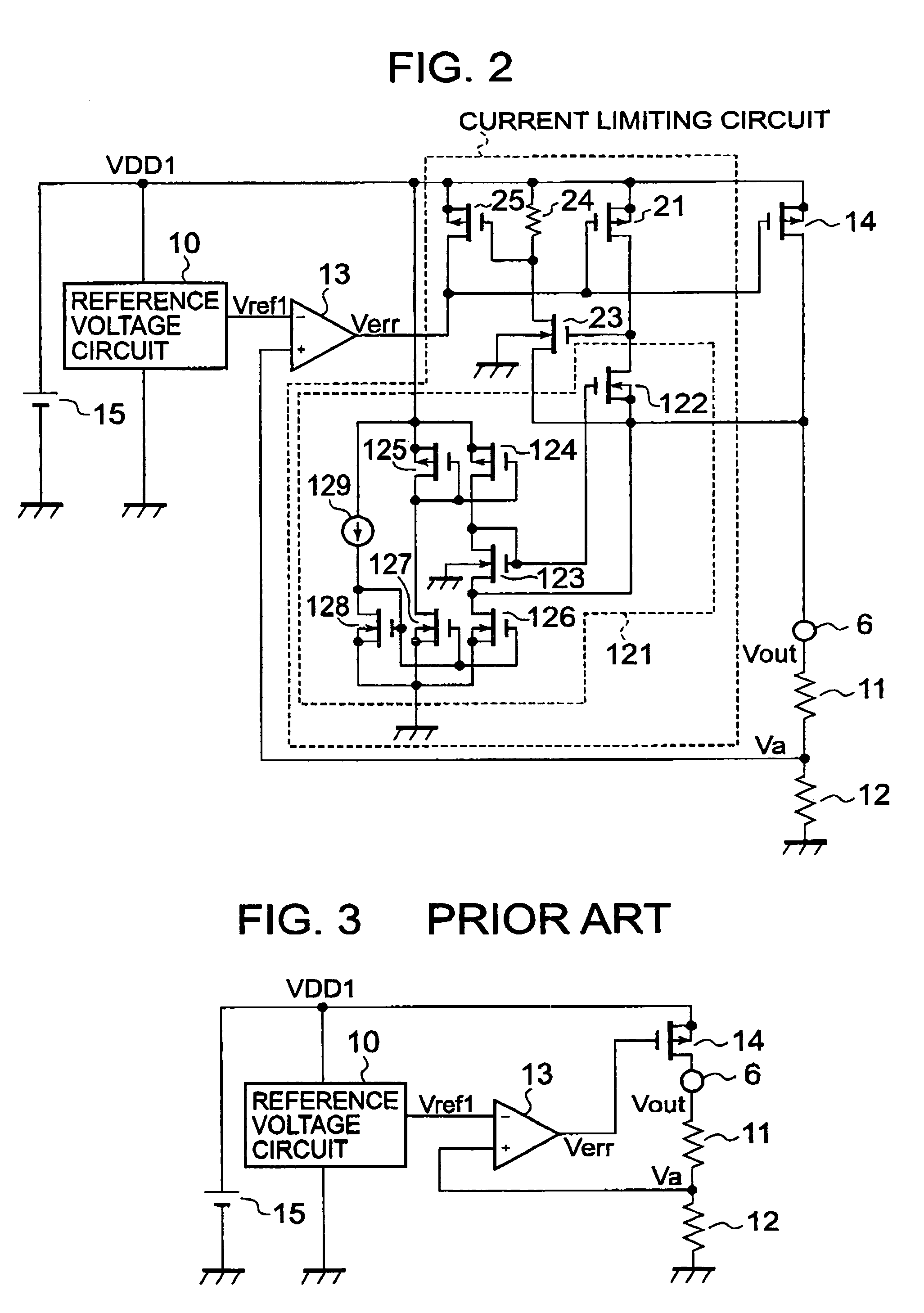
[0021]FIG. 1 is a circuit diagram showing a configuration of a voltage regulator according to an embodiment of the present invention. The voltage regulator according to this embodiment of the present invention is provided with a current limiting circuit including a P-channel MOS transistor 21 connected with an output P-channel MOS transistor 14 to make a current mirror circuit, a current source circuit 121 connected between the P-channel MOS transistor 21 and an output terminal 6, and a P-channel MOS transistor 25 connected between a power supply 15 for supplying a power supply voltage VDD1 and an output terminal of an error amplifier 13.

[0022]That is, the feature of the voltage regulator according to this embodiment of the present invention resides in that the current source circuit 121 is used instead of the resistor 22 of the current limiting circuit of the conventional voltage regulator (refer to FIG. 4). A current value of the current source circuit 121 is designed so as to dec...


PUM


Abstract

A voltage regulator has an output MOS transistor connected between a voltage source and an output terminal. A voltage dividing circuit is disposed between the output terminal and GND. An error amplifier receives a reference voltage from a reference voltage circuit and a division voltage from the voltage dividing circuit. A current limiting circuit is disposed between the voltage source and the output terminal. The current limiting circuit has a first MOS transistor connected to the voltage source. A current source circuit is disposed between the first MOS transistor and the output terminal. A resistor is connected to the voltage source. A second MOS transistor is controlled based on a current caused to flow through the first MOS transistor. A third MOS transistor is connected between the voltage source and an output terminal of the error amplifier and is controlled based on a current caused to flow through the resistor. When a current caused to flow through the first MOS transistor reaches a predetermined current, the current limiting circuit controls the output MOS transistor to limit a current outputted through the output terminal.

Description

BACKGROUND OF THE INVENTION[0001]1. Field of the Invention[0002]The present invention relates to a voltage regulator which is capable of suppressing dispersion in an output short circuit current of the voltage regulator.[0003]2. Description of the Related Art[0004]FIG. 3 shows a circuit diagram of a conventional voltage regulator. The conventional voltage regulator includes: a voltage regulator control circuit having a reference voltage circuit 10, bleeder resistors 11 and 12 through which an output voltage Vout at an output terminal 6 is divided, and an error amplifier 13 for amplifying a difference between a reference voltage Vref1 and the division voltage; and an output P-channel MOS transistor 14. The conventional voltage regulator is operated with a voltage VDD1 supplied from a voltage source 15.[0005]When an output voltage from the error amplifier 13 is assigned Verr, and a voltage at a node between the bleeder resistors 11 and 12 is assigned Va, if Vref1>Va, the output vol...

Claims


Application Information

Patent Timeline
Patent Type & Authority Patents(United States)
IPC IPC(8): G05F1/569G05F1/56G05F1/40G05F1/565
CPCG05F1/565G05F1/56
Inventor SUGIURA, MASAKAZU
Owner ABLIC INC
Why Eureka
Try Eureka