Disk drives, head stack, head gimbal and suspension assemblies having positional conductive features

Inactive Publication Date: 2008-01-01
WESTERN DIGITAL TECH INC
View PDF2 Cites 49 Cited by
  • Summary
  • Abstract
  • Description
  • Claims
  • Application Information

AI Technical Summary

Benefits of technology

[0019]The pair of conductive features may be aligned with the opening within the flexure such that the angle is substantially 180 degrees, for ex

Problems solved by technology

However, because the dimple is formed relative to features (e.g., cutouts and other registration features) of the load beam and as the bonding

Method used


Image

  • Disk drives, head stack, head gimbal and suspension assemblies having positional conductive features
  • Disk drives, head stack, head gimbal and suspension assemblies having positional conductive features
  • Disk drives, head stack, head gimbal and suspension assemblies having positional conductive features

Examples


Embodiment Construction

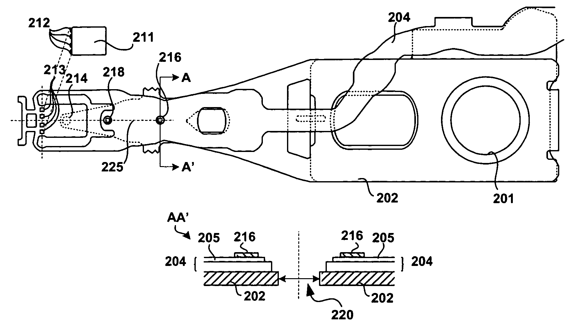
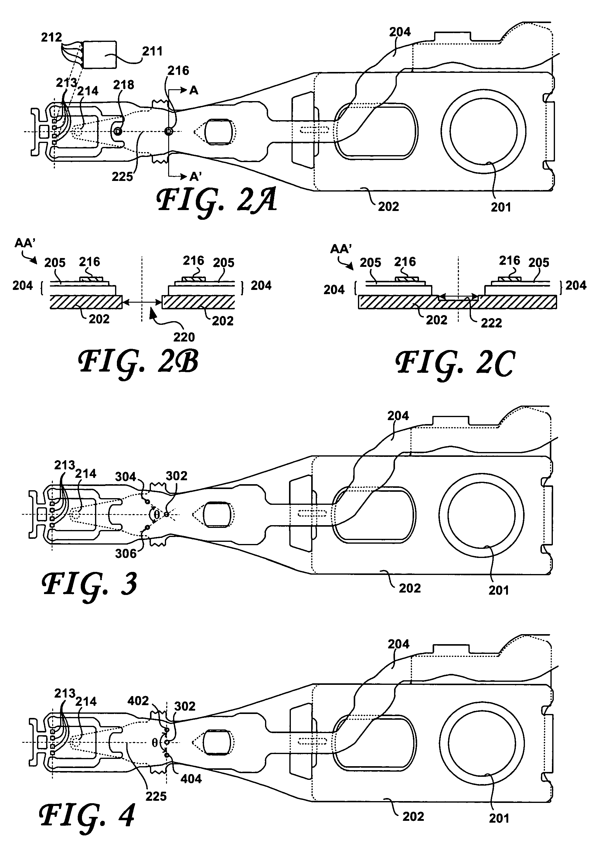
[0027]FIG. 2A shows a head gimbal assembly, according to an embodiment of the present invention. FIG. 2B is a cross-sectional view of a conductive feature according to an embodiment of the present invention, taken along cross-sectional line AA′ in FIG. 2A. FIG. 2C is a cross-sectional view of a conductive feature according to another embodiment of the present invention, taken along cross-sectional line AA′ in FIG. 2A. FIGS. 3 and 4 show further embodiments of the present invention. Considering now FIGS. 2A, 2B, 2C, 3 and 4 collectively, the HGA includes a load beam 202 that may attach to an actuator arm (shown in FIG. 5) of an HSA (also shown in FIG. 5) through, for example, a swaging process through an opening 201 defined within the load beam 202. The TSA includes a flexure 204 that is coupled to the load beam 202. The dimple 214, shown in FIGS. 2A, 3 and 4, is formed within the load beam 202, at the distal free end thereof.

[0028]The load beam 202 may include one or more load beam ...


PUM


Abstract

A disk drive includes a disk, and a head stack assembly (HSA). The HSA includes a preamplifier; an actuator assembly that defines an actuator arm; a load beam supported by the actuator arm, the load beam defining a registration feature. A flexure is coupled to the load beam, the flexure defining an opening that is centered on the registration feature and including a plurality of conductive formations. The conductive formations include a plurality of conductive flexure connection pads that collectively define a center point; a plurality of conductive traces to electrically couple the plurality of flexure connection pads to the preamplifier, and a conductive feature disposed away from and aligned with the center point, the conductive feature at least partially surrounding the opening within the flexure. A slider is coupled to the plurality of flexure connection pads for reading and writing to the disk.

Description

BACKGROUND OF THE INVENTION[0001]1. Field of the Invention[0002]The present invention relates to disk drives. More particularly, the present invention relates to disk drives, head stack, head gimbal and suspension assemblies that include conductive features used for alignment and placement of load beam and / or flexure features.[0003]2. Description of the Prior Art[0004]A typical hard disk drive includes a head disk assembly (“HDA”) and a printed circuit board assembly (“PCBA”). The HDA includes at least one magnetic disk (“disk”), a spindle motor for rotating the disk, and a head stack assembly (“HSA”) that includes a slider with at least one transducer or read / write element for reading and writing data. The HSA is controllably positioned by a servo system in order to read or write information from or to particular tracks on the disk. The typical HSA has three primary portions: (1) an actuator assembly that moves in response to the servo control system; (2) a head gimbal assembly (“H...

Claims


Application Information

Patent Timeline
IPC IPC(8): G11B5/55
CPCG11B5/4853
Inventor PAN, TZONG-SHII
Owner WESTERN DIGITAL TECH INC
Why Eureka
Try Eureka