Air circulating shoe pad

a technology of air circulation and shoe pads, which is applied in the direction of shoes, insoles, heels, etc., can solve the problems of hot, humid, uncomfortable shoes worn in warm weather

Inactive Publication Date: 2008-01-08
CHENG KAN
View PDF15 Cites 50 Cited by
  • Summary
  • Abstract
  • Description
  • Claims
  • Application Information

AI Technical Summary

Problems solved by technology

A shoe worn in warm weather...

Method used


Image

  • Air circulating shoe pad
  • Air circulating shoe pad
  • Air circulating shoe pad

Examples


Embodiment Construction

FIG. 1

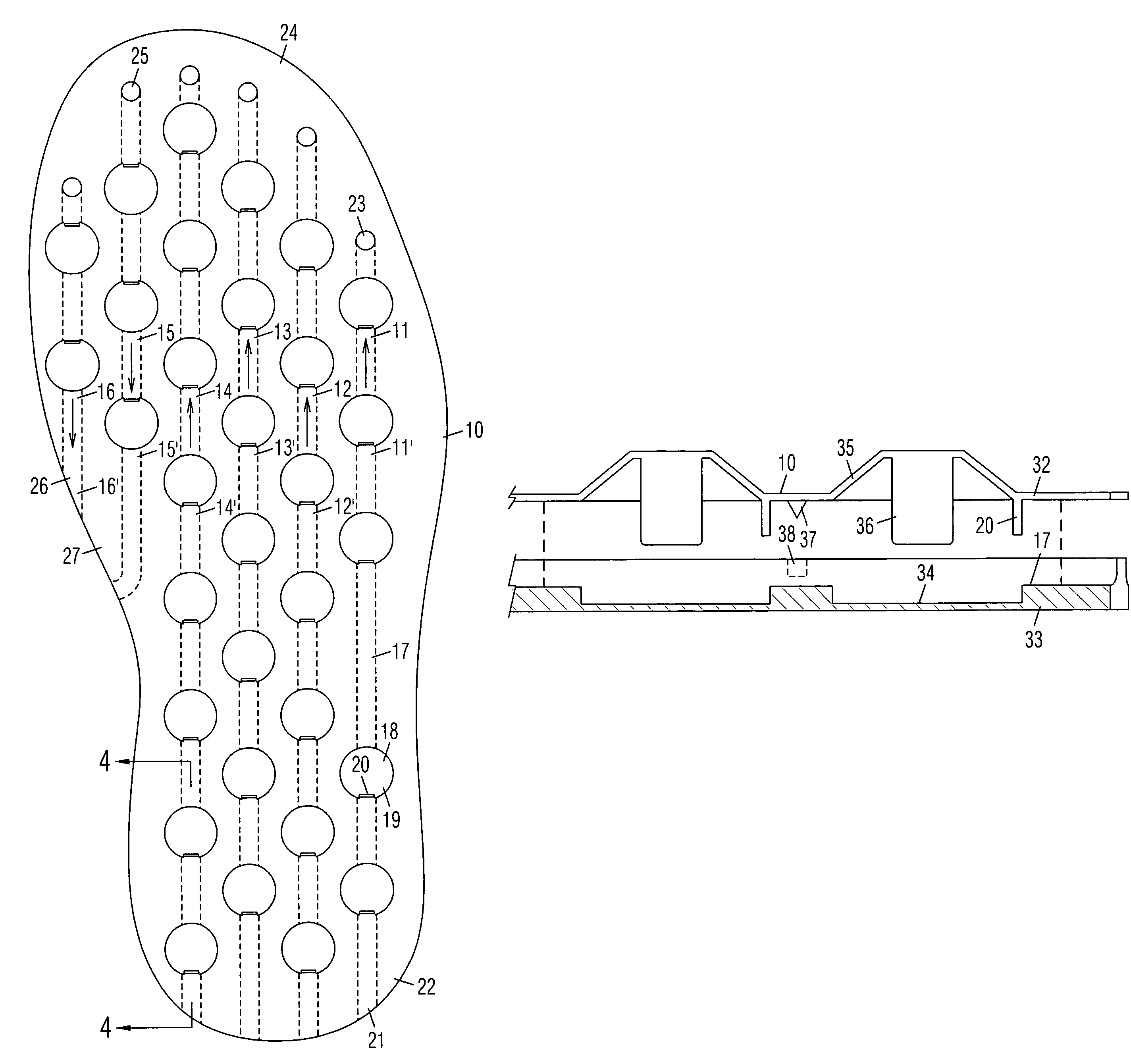
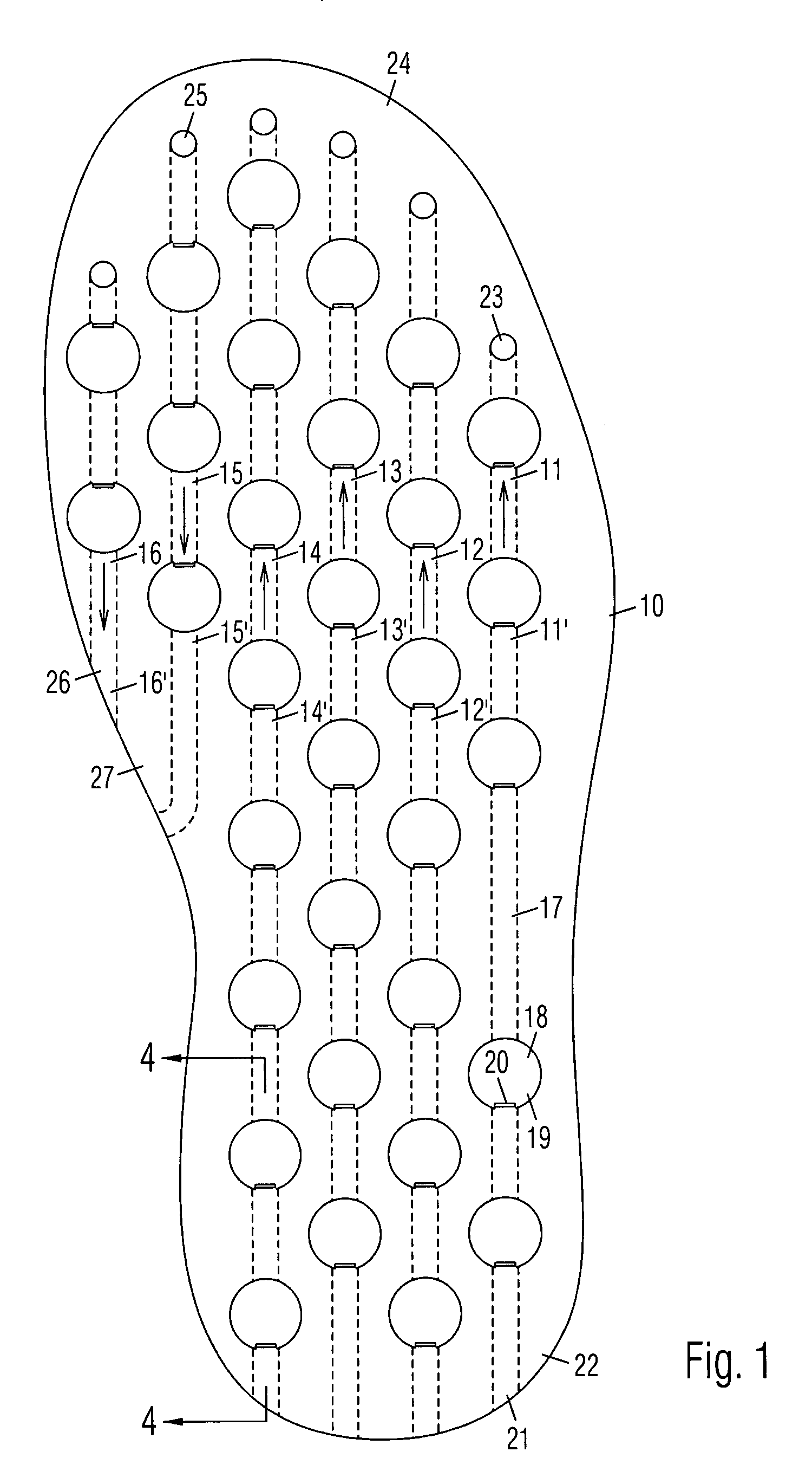
[0014]An air circulating shoe pad 10 includes a plurality of air pumping elements 11-16 for cooling the interior of a shoe. Each pumping element is comprised of a longitudinal internal channel 17 with a plurality of pumps 18 arranged in a series along channel 17. Each pump 18 is comprised of a resilient blister 19 on top of pad 10, and a one-way flap valve 20. Each pumping element may have more or fewer pumps than shown. The pumping power of the series connected pumps are combined for increasing air flow. Pumping elements 11-16 are separate from each other.

[0015]As indicated by the air flow direction arrows, pumping elements 11-14 include forward pumping elements 11′-14′ which pump air from back to front, and rearward pumping elements 15′-16′ which pump air from front to back. Forward pumping elements 11′-14′ have intakes 21 adjacent a heel portion 22 of pad 10 and exhausts 23 adjacent a toe portion 24 of pad 10. Rearward pumping elements 15′-16′ have intakes 25 adjacent toe p...


PUM


Abstract

A shoe pad includes air pumping elements for cooling the interior of a shoe. The pumping elements include forward pumping elements for pumping air from back to front, and backward pumping elements for pumping air from front to back. The pad includes an upper sheet attached to a lower sheet. Each pumping element includes a channel on the lower sheet covered by the upper sheet. The channel has an intake and an exhaust. Cavities are distributed along the channel. Resilient blisters on the upper sheet are aligned with the cavities on the lower sheet to define pumps. Each pump has an intake and an exhaust. Flap valves projecting down from the upper sheet are respectively positioned against the intakes of the pumps. Alignment pins projecting down from the top sheet are positioned in alignment holes on the lower sheet.

Description

BACKGROUND OF THE INVENTION[0001]1. Field of the Invention[0002]The invention broadly relates to devices for circulating air inside shoes.[0003]2. Prior Art[0004]A shoe worn in warm weather is hot, humid and uncomfortable. Therefore, many devices for circulating air inside a shoe have been invented. U.S. Pat. No. 6,671,979 discloses a pump connected to air channels for recirculating air drawn in through an intake, but there is no exhaust port for expelling the hot air. U.S. Pat. No. 220,475 discloses a shoe cooled by air channels with a port adjacent the heel and another port in the sole, but has no pump for moving air through the channels. US published patent application 2004 / 0078996 discloses a shoe with resilient tubes in the sole open to opposite edges of the sole, but the tubes have no valve for directing airflow. U.S. Pat. No. 2,474,815 discloses a shoe pad with an intake and a discharge valve feeding a manifold, but there is no apparent connection between the valves. U.S. Pat...

Claims


Application Information

Patent Timeline
IPC IPC(8): A43B7/06A43B13/20A43B21/28
CPCA43B7/08A43B17/08
Inventor CHENG, KAN
Owner CHENG KAN
Why Eureka
Try Eureka