Electric control valve

a technology of electric control valve and valve body, which is applied in the direction of valve operating means/releasing devices, refrigeration components, light and heating apparatus, etc., can solve the problems of large increase so as to reduce reduce the friction drag of rotating the valve body. , the effect of increasing the driving torque of the valve body

Active Publication Date: 2008-01-08
SAGINOMIYA SEISAKUSHO INC
View PDF17 Cites 19 Cited by
  • Summary
  • Abstract
  • Description
  • Claims
  • Application Information

AI Technical Summary

Benefits of technology

[0006]There is a drawback that, according to the above electric control valve, a frictional drag of rotating of the valve body is large since the valve body rotates in a condition that the end surface of the valve body contacts with the flat valve seat surface, and when the valve body has a larger outer diameter, an area of contact surface thereof becomes larger and a driving torque of the valve body increases.
[0007]To overcome the above drawback, one object of this invention is to provide an electric control valve, in which the driving torque of the valve body can be reduced, and valve leakage is prevented by high flatness of the valve seat surface.

Problems solved by technology

There is a drawback that, according to the above electric control valve, a frictional drag of rotating of the valve body is large since the valve body rotates in a condition that the end surface of the valve body contacts with the flat valve seat surface, and when the valve body has a larger outer diameter, an area of contact surface thereof becomes larger and a driving torque of the valve body increases.

Method used


Image

  • Electric control valve
  • Electric control valve
  • Electric control valve

Examples


second embodiment

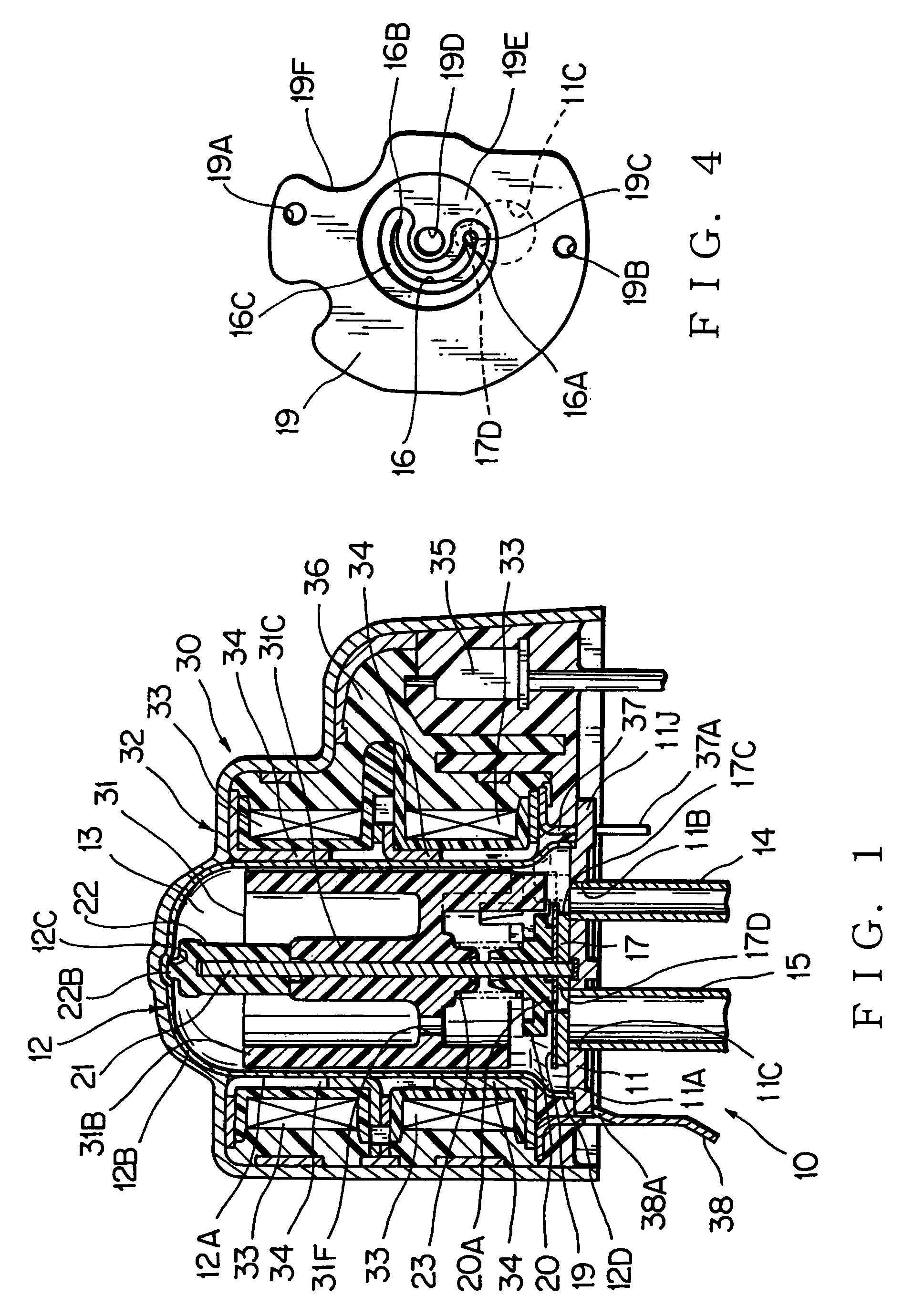
Physical Structure of an Electric Control Valve According to the Present Invention

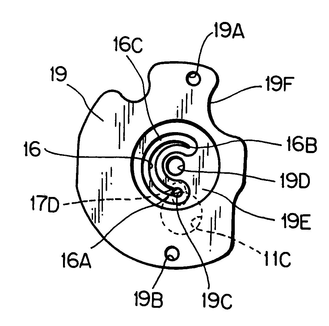
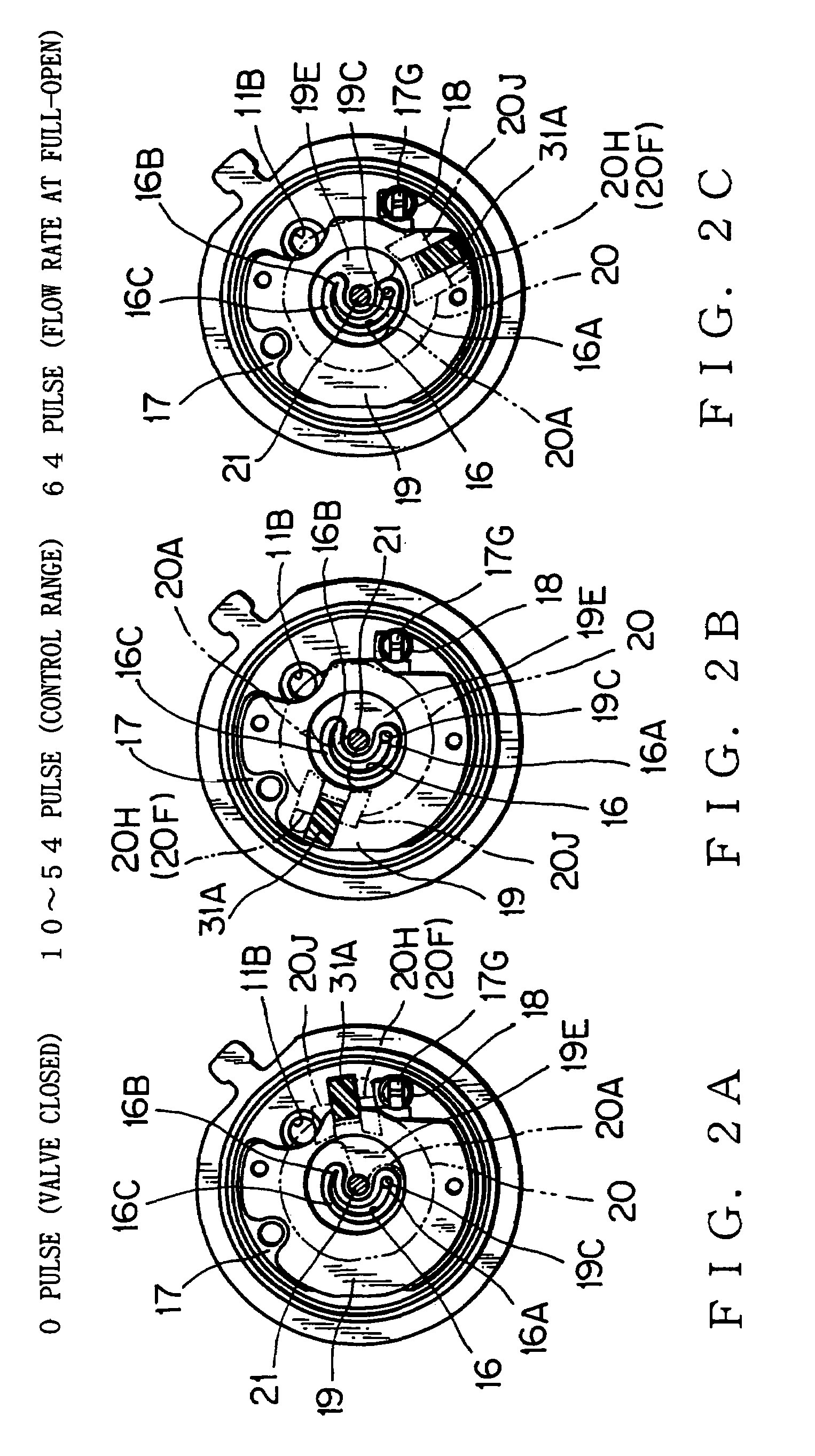
[0072]An electric control valve according to the second embodiment of the present invention is described with reference to FIGS. 12A, 12B, 12C and 13. Parts in FIGS. 12A-12C corresponding to FIGS. 2A-2C are put with the same markings and explanation will be omitted.

[0073]A different point between the second embodiment and aforesaid first embodiment is the opposite of characteristics of values of rotating valve body (number of pulses) and flow rate, clearly by comparing FIG. 13 showing the characteristics of values of rotating valve body (number of pulses) of the electric control valve in FIG. 12 and the flow rate and FIG. 8 showing the characteristics of the electric control valve of the first embodiment. So that as shown in FIG. 12A, the full-open port 19C is opened to be in a full-open condition by 0 pules, and as shown in FIG. 12B, the valve body is in a control range to determine throttled flow rat...


PUM


Abstract

The electric control valve, in which a throttled flow rate is quantitatively determined by the groove 16 by a rotating position of the valve body 20, the valve seat surface projects like a band from a border band 16C drawing an outline of the groove 16, and the end surface of the valve body 20 contacts slidingly on a top surface of the border band 16C.

Description

REFERENCE TO RELATED APPLICATIONS[0001]This application claims the benefit of Japanese Patent Application No. 2003-037314 filed on Feb. 14, 2003, and to Japanese PCT Application No. PCT / JP2004 / 001542 filed on Feb. 13, 2004.BACKGROUND OF THE INVENTION[0002]1. Field of the Invention[0003]This invention relates to an electric control valve, especially, the electric control valve used as an electric expansion valve and a flow control valve for a freezing chamber and a refrigerating chamber.[0004]2. Description of the Related Art[0005]As the electric control valve used as the electric expansion valve and the flow control valve at a coolant flow path of the freezing / refrigerating chamber, a one-revolution type electric control valve, which includes a groove extending in a circular arc shape in a rotating direction of the valve body on a slid-contact surface (an end surface) opposing to a valve seat surface of the valve body, and changing gradually one of a width and a depth of the groove ...

Claims


Application Information

Patent Timeline
Patent Type & Authority Patents(United States)
IPC IPC(8): F16K31/12F16K11/074F16K31/04F25B41/06
CPCF16K11/0743F16K31/041F25B41/062F25B2341/065Y02B30/72Y02B30/70F25B41/34F25B41/35F25B41/31
Inventor SEKIYA, ITARUKOHNO, ATSUKANEKO, MORIO
Owner SAGINOMIYA SEISAKUSHO INC
Why Eureka
Try Eureka