Drive Arrangement For Vehicles With At Least Two Drivable Vehicle Axles

Active Publication Date: 2008-11-13
AGCO GMBH
View PDF6 Cites 14 Cited by
  • Summary
  • Abstract
  • Description
  • Claims
  • Application Information

AI Technical Summary

Benefits of technology

[0041]Preferably a control unit, which actuates the first clutch, is provided so that the propulsive connection of the de-connectable hydraulic motor is disconnected from the associated vehicle axle before a maximum permissible rotational speed of the de-connectable hydraulic motor is reached. Thus substantial friction and leakage losses, which are caused by the hydraulic motor in the high-speed range, are avoided. Disconnection of the hydraulic motor is preferably controlled in combination with the continuous reduction of the piston stroke of this de-connectable hydraulic motor with increasing driving speed, as described above.
[0042]In an advantageous further embodiment of the present invention a control unit, which actuates the first clutch, is provided so that it disconne

Problems solved by technology

Nevertheless, when travelling over rough terrain, it may occur that the driven wheels lose their capacity to transmit tractive force and spin with extremely one-sided axle load distribution and high traction power demand.
Such hydraulic motors and/or translations are usually not designed for high rotatio

Method used


Image

  • Drive Arrangement For Vehicles With At Least Two Drivable Vehicle Axles
  • Drive Arrangement For Vehicles With At Least Two Drivable Vehicle Axles
  • Drive Arrangement For Vehicles With At Least Two Drivable Vehicle Axles

Examples


second embodiment

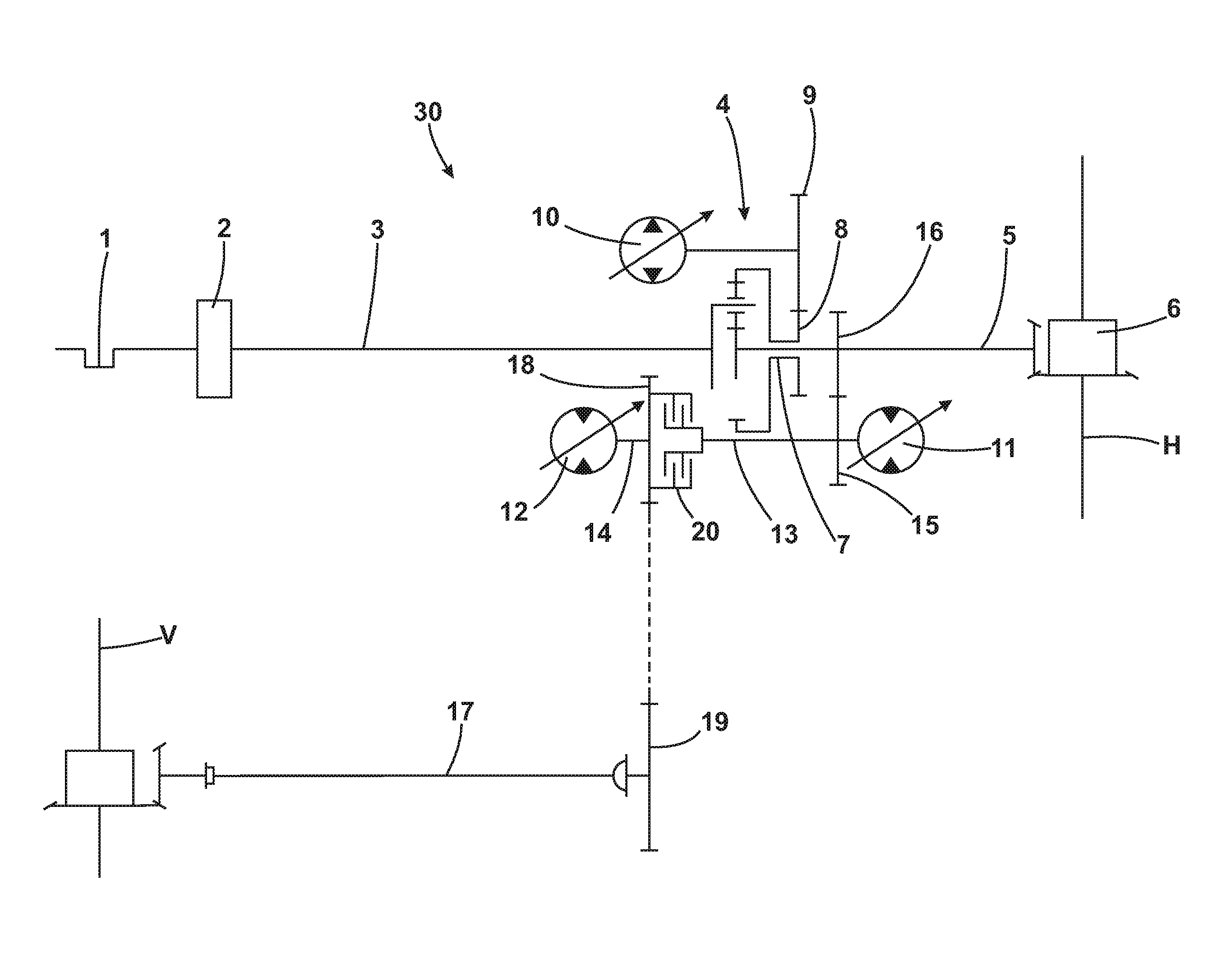
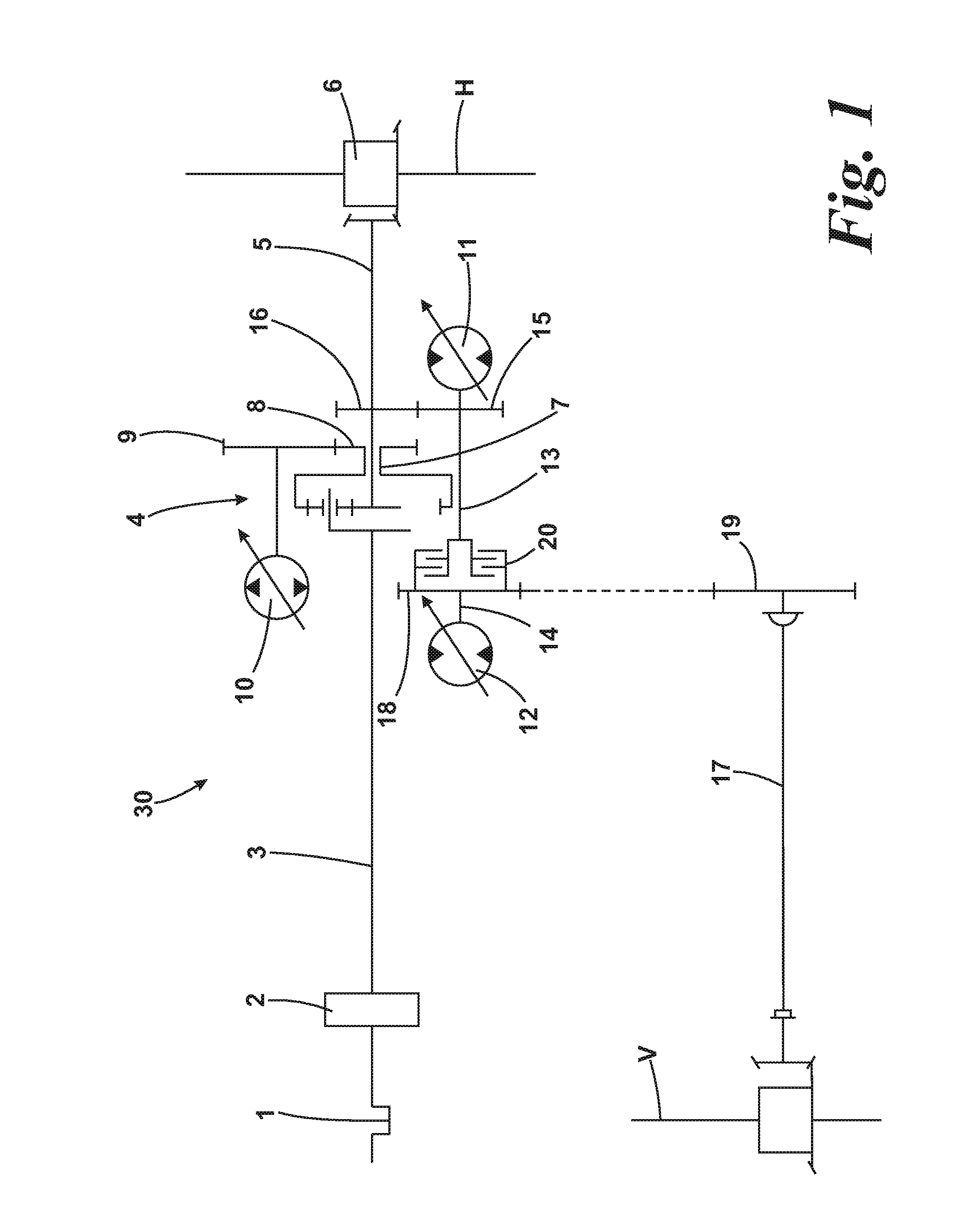
[0058]FIG. 4 illustrates a drive 60. Only the differences in relation to the embodiment illustrated in FIG. 3 are discussed in detail below. In the case of the drive 60 no power branched transmission, as formed in FIG. 3 by the planetary transmission 4, is provided. By contrast the entire drive power of the input shaft 3 is transmitted via a gear wheel stage 8′, 9′ to the hydraulic pump 10. The adjustable hydraulic pump 10 in turn drives the two parallel-connected hydraulic motors 11, 12 via (not illustrated) hydraulic lines. The hydraulic motor 11 is thereby constantly propulsively connected via the gear wheel stage 15, 16 to the rear axle H. Contrary to the embodiment illustrated in FIG. 3 a component of the drive power of the internal combustion engine 1 directly branched off from the input shaft 3 is not additionally fed to the rear axle H.

[0059]The arrangement of the hydraulic motors 11, 12 and the clutches 20, 22 in all other respects corresponds to the arrangement illustrated...

third embodiment

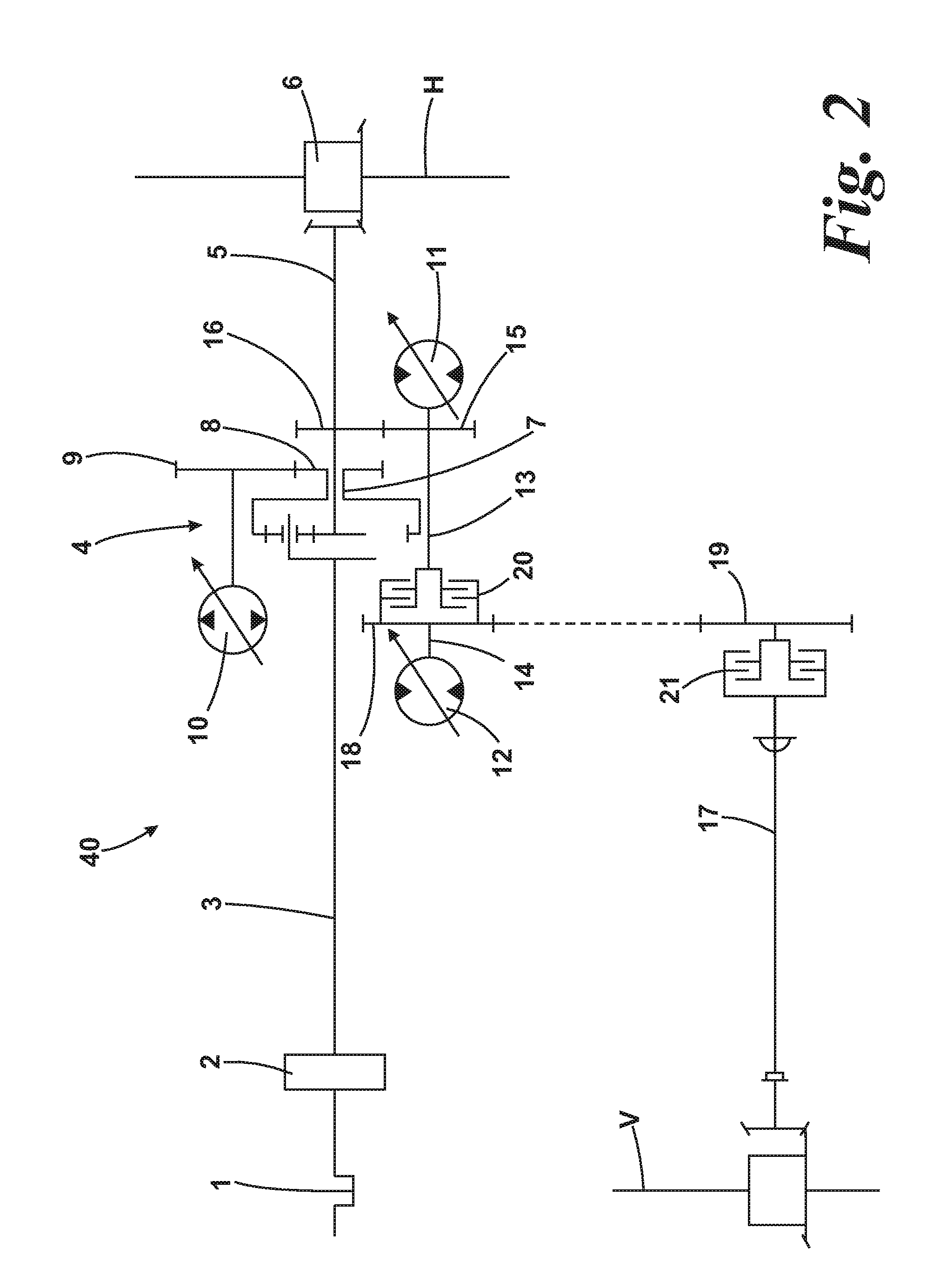
[0060]FIG. 5 illustrates a drive 70 with a drive arrangement according to the present invention. Only the differences in relation to the embodiment illustrated in FIG. 3 are discussed in below. As in the case of the drive 50 shown in FIG. 3, the hydraulic motor 11 can be propulsively connected via the second clutch 20 and gear wheel stage 18, 19 to the power train of the front vehicle axle V. In contrast to the embodiment illustrated in FIG. 3 the de-connectable hydraulic motor 12 is not propulsively connected via the first clutch 22 to the gear wheel stage 18, 19 but connected to a separately formed gear wheel stage 23, 24. The gear wheel stage 23, 24 in this case has a large translation, so that high torque can be transmitted from the hydraulic motor 12 to the front vehicle axle V. As explained above, particularly at low driving speeds, high torque can therefore be transmitted via the de-connectable hydraulic motor 12 to the front axle V so that high traction forces are produced o...


PUM


Abstract

The present invention relates to a drive arrangement for vehicles with at least two drivable vehicle axles (V, H). The drive arrangement is particularly suitable for utility vehicles and agricultural tractors. It has at least one first motor (11), which is propulsively connected to a first vehicle axle (H), and a second motor (12), which is propulsively connected to a second vehicle axle (V). At least one of the motors is a de-connectable motor (12), which can be disconnected from the propulsive connection to the associated vehicle axle (V). Regardless of whether the de-connectable motor (12) is propulsively connected to the associated vehicle axle (V) or is propulsively disconnected therefrom, a propulsive connection can be selectively made and broken between the first and the second vehicle axle (V, H).

Description

CROSS REFERENCE TO RELATED APPLICATION[0001]This application is based on, and claims the benefit of priority to, German application DE 10 2007 021 733.3, filed 9 May 2007, which priority application is hereby incorporated by reference.BACKGROUND OF THE INVENTION[0002]1. Field of Invention The present invention relates to a drive arrangement for vehicles with at least two drivable vehicle axles, wherein the drive arrangement comprises at least one first motor, which is propulsively connected to a first vehicle axle, and a second motor, which is propulsively connected to a second vehicle axle. The drive arrangement according to the invention is particularly suitable for utility vehicles and agricultural tractors.[0003]2. Description of Related Art[0004]Utility vehicles, particularly agricultural utility vehicles such as for example a farm tractor, frequently have at least two drivable vehicle axles. Also passenger cars, which are designed to travel over wet or smooth roadways and off-...

Claims


Application Information

Patent Timeline
IPC IPC(8): F16H37/08B60K17/356
CPCB60K17/356B60K23/0808F16H2047/045F16H61/456F16H2037/0866F16H47/04
Inventor HEINDL, RICHARD
Owner AGCO GMBH
Why Eureka
Try Eureka