Frictional resistance generation mechanism

a generation mechanism and friction resistance technology, applied in the direction of yielding coupling, vibration suppression adjustment, flywheel, etc., can solve the problems of low engine torque, abnormal transmission of vehicles, and considerable torque fluctuation

Inactive Publication Date: 2004-12-09
EXEDY CORP
View PDF5 Cites 12 Cited by
  • Summary
  • Abstract
  • Description
  • Claims
  • Application Information

AI Technical Summary

Problems solved by technology

A vehicle commonly emits abnormal, i.e. deviating from a standard, noises during idling (rattling noise), abnormal noises while running (acceleration / deceleratio-n rattling, booming noise), and tip-in / tip-out noise (low frequency vibration).
An abnormal noise while idling is a noise that can be heard as a "rattle" generated by the transmission when shifted into the neutral gear and the clutch pedal is released while waiting at a traffic light or the like.
The reason for this abnormal noise is that the engine torque is low in the vicinity of engine idling rotation, and torque fluctuation is considerable during engine firing.
Rattling noise occurs between the counter gear and input gear of the transmission at this time.
When the rigidity of the drive transmission system is low, the torque transmitted to the tires is conversely transmitted to the drive transmission system from the tires, and excessive torque is generated in the tires as a backlash.
The result is a longitudinal vibration that violently and transiently shakes the car body in the longitudinal direction.
The torsion characteristics of a conventional clutch disk assembly are insufficient in the vicinity of the zero torque to counter the abnormal noise during idling because the torsional rigidity at this point should be low.
Further, at this time, the frictional resistance generating unit does not operate.
As a result, the knocking sound of the pawl decreases when a high hysteresis torque is generated in the frictional resistance generating mechanism.
However, the low-friction generation member slides in relation to the second rotating member, and a small amount of friction is generated.
As a result, the high-friction generating member generates large friction.
Therefore, the hysteresis torque gradually increases, and, as a result, the buildup of hysteresis torque decreases the instant that the subsequent frictional member operates.
As a result, high hysteresis torque is not generated for small torsional vibrations.

Method used


Image

  • Frictional resistance generation mechanism
  • Frictional resistance generation mechanism
  • Frictional resistance generation mechanism

Examples


second embodiment

[0137] (4) Second Embodiment

[0138] Another embodiment of the frictional resistance generation mechanism is described below with reference to FIGS. 14 to 17. The frictional resistance generation mechanism 107 is a mechanism that functions in parallel with a coil spring (not depicted) between a disk-like member 113 and output side disk-like plates 130 and 131 in the direction of rotation. When a flywheel 121 with a friction surface rotates relative to the crankshaft, a prescribed frictional resistance (hysteresis torque) is generated.

[0139] An annular first inertia member and second inertia member 114A and 114B are fixed to the radially outer portion of the disk-like member 113. The first inertia member 114A is disposed on the axial direction engine side, and the second inertia member 114B is disposed on the axial direction transmission side relative to each other. A disk-like plate member 115 is fixed between the first inertia member 11 4A and the second inertia member 114B. The radi...

third embodiment

[0159] (5) Third Embodiment

[0160] Another embodiment of the frictional resistance generation mechanism is described below with reference to FIGS. 18 to 21. Description of identical portions of the above-described embodiments is omitted.

[0161] 5-1) Frictional Resistance Generation Mechanism 207

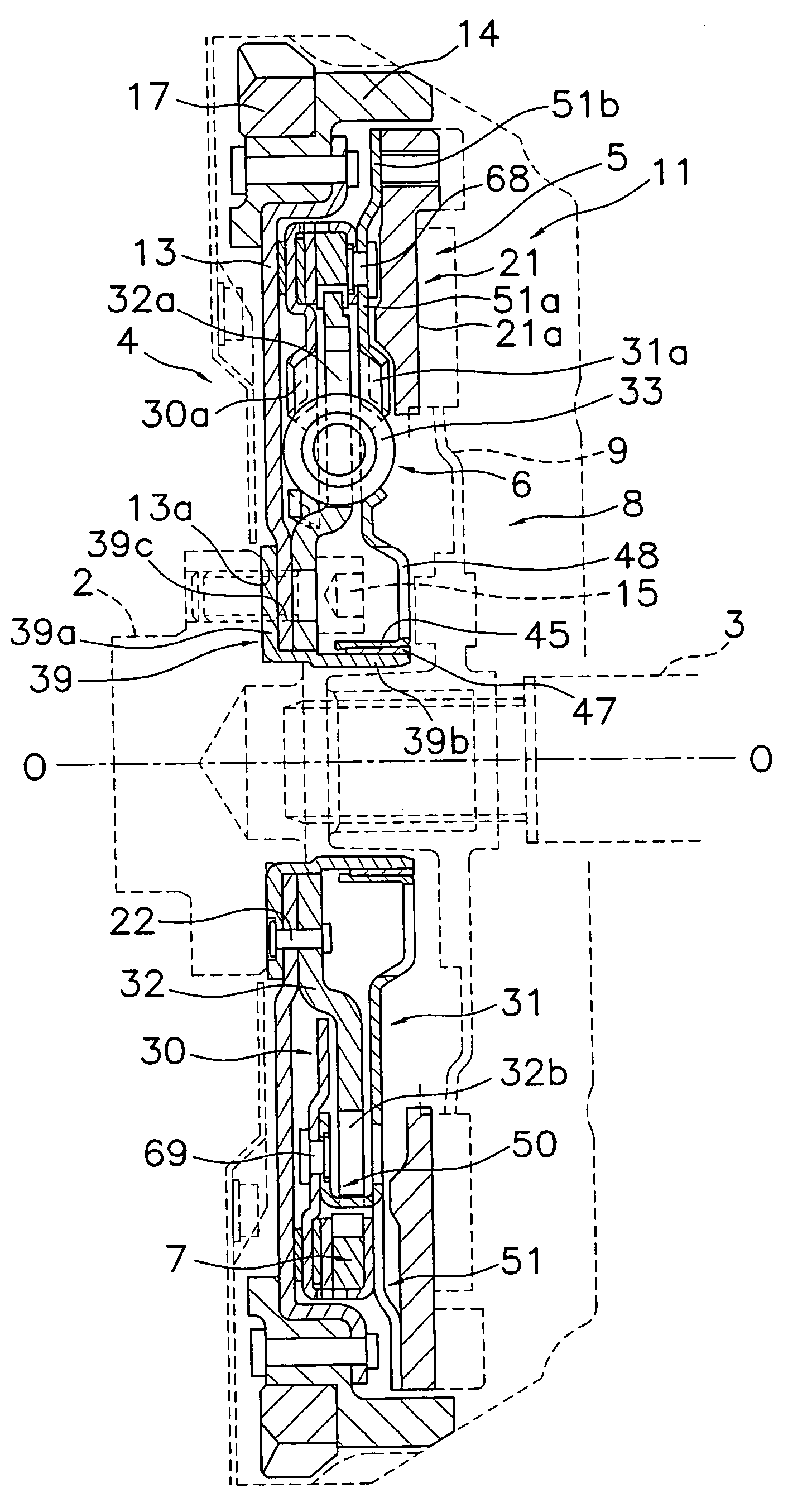
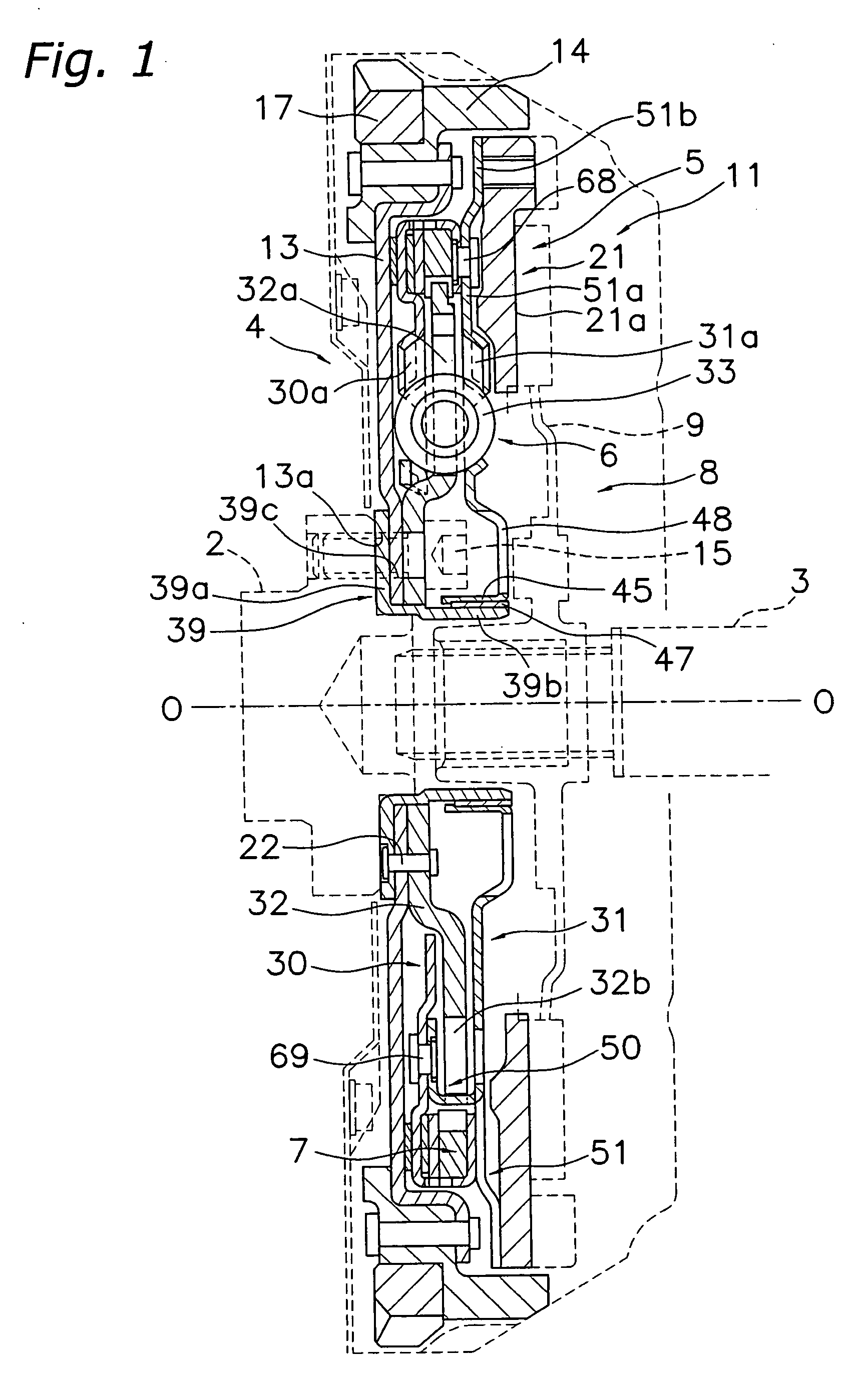
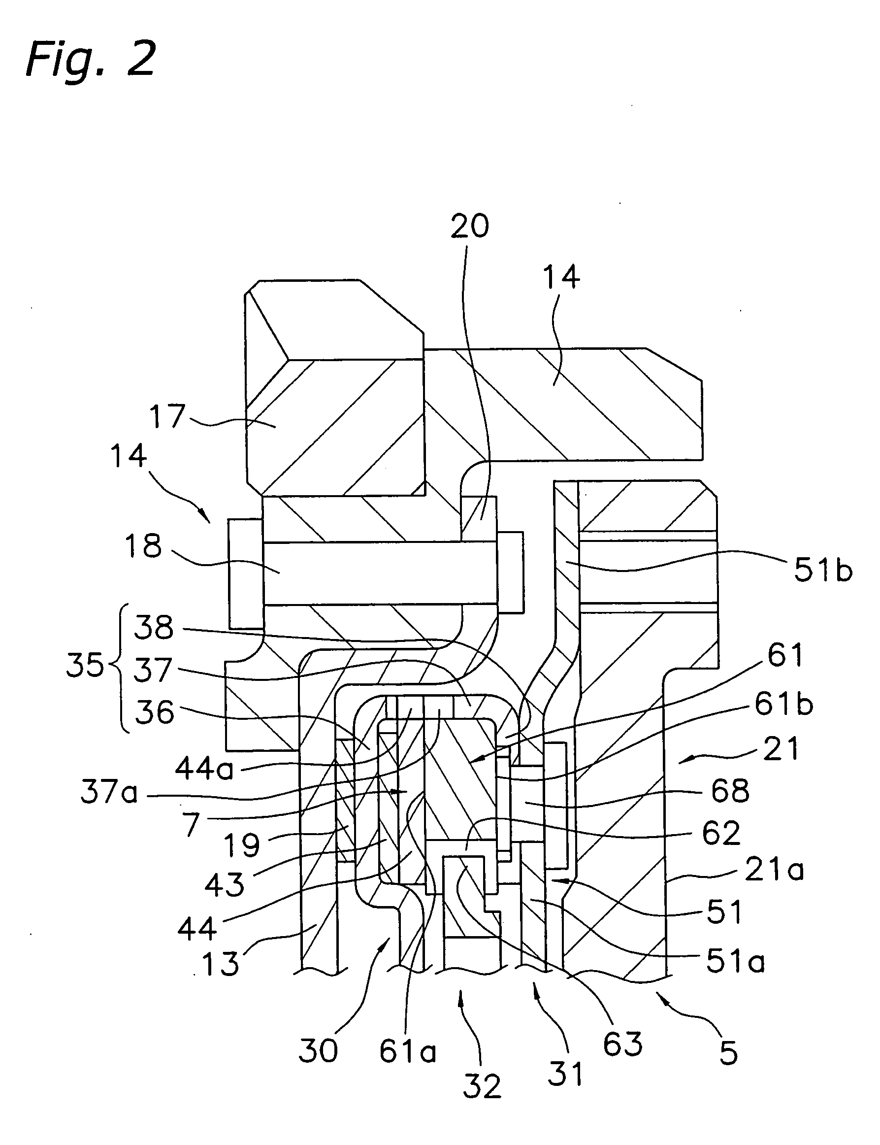
[0162] As seen in FIG. 18, a frictional resistance generation mechanism 207 functions in parallel with coil springs between output side disk-like plates 232 and 233 and an input side disk-like plate 212 of a damper mechanism in the direction of rotation. Further, when a second flywheel 203 rotates relative to the crankshaft, a prescribed frictional resistance (hysteresis torque) is generated. The frictional resistance generation mechanism 207 generates a constant friction over an entire range of operating angles of the damper mechanism, and is designed to generate comparatively large frictional resistance.

[0163] The frictional resistance generation mechanism 207 is disposed in the space formed ...

fourth embodiment

[0186] (6) Fourth Embodiment

[0187] A friction resistance generation mechanism 307 related to a fourth embodiment of the present invention is described below with reference to FIGS. 22 to 27. In this embodiment, the basic structure of the friction resistance generation mechanism 307 is the same as the friction resistance generation mechanism 207 in the above-described embodiment. A description of identical portions is omitted below, and emphasis is placed on portions that differ.

[0188] The widths in the direction of rotation (the angles in the direction of rotation) of friction engagement members 363 are all the same, but some of the widths in the direction of rotation (the angles in the direction of rotation) of the concavities 362 may be different. That is to say, there are at least three types of friction shims 361 with differing widths in the direction of rotation of the concavities 362. In this embodiment, these are composed of two first friction shims 361A that face each other ...


PUM


Abstract

A friction resistance generation mechanism is disposed between two relatively rotatable members of a rotating mechanism. The mechanism includes an input side disk-like plate 32, output side disk-like plates 30 and 31, first friction shims 61A, and second friction shims 61B. The first friction shims 61A are frictionally engaged with the plates 30 and 31, and engaged in a manner that allows torque to be transmitted by way of a first rotational direction gap 79A to the plate 32. The second friction shims 61B are frictionally engaged with the plates 30 and 31, and engaged in a manner that allows torque to be transmitted to the plate 32 by way of a second rotational direction gap 79B with a different size than the first rotational direction gap 79A.

Description

[0001] 1. Field of the Invention[0002] The present invention relates to a frictional resistance generation mechanism. More specifically, the present invention relates to a mechanism for attenuating torsional vibration that is disposed between two relatively rotatable members of a rotating mechanism, and is designed to generate frictional resistance and to attenuate the torsional vibration due to the torsional friction when the two members rotate relative to each other.[0003] 2. Background Information[0004] A clutch disk assembly used in vehicles has a clutch function for engaging or disengaging a flywheel, and a damper function for absorbing and attenuating torsional vibration from the flywheel. A vehicle commonly emits abnormal, i.e. deviating from a standard, noises during idling (rattling noise), abnormal noises while running (acceleration / deceleratio-n rattling, booming noise), and tip-in / tip-out noise (low frequency vibration). It is a function of the damper of the clutch disk ...

Claims


Application Information

Patent Timeline
Patent Type & Authority Applications(United States)
IPC IPC(8): F16F15/129F16F15/139F16F15/30
CPCF16F15/139
Inventor TSURUTA, HIROYOSHIUEHARA, HIROSHI
Owner EXEDY CORP
Why Eureka
Try Eureka