
Heat trace or control cable support with insulating jackets

a technology of control cable and heat trace, which is applied in the direction of insulated conductors, cables, conductors, etc., can solve the problems of heat trace cables that are continuously damaged by friction, heat trace cables that are found to sustain damage from friction, and insulation blankets being removed, so as to avoid significant friction in the wiring cable, facilitate the entrance and exit, and the effect of flexibleness

Active Publication Date: 2009-02-03
MARATHON PETROLEUM
View PDF4 Cites 12 Cited by
  • Summary
  • Abstract
  • Description
  • Claims
  • Application Information

AI Technical Summary

Benefits of technology

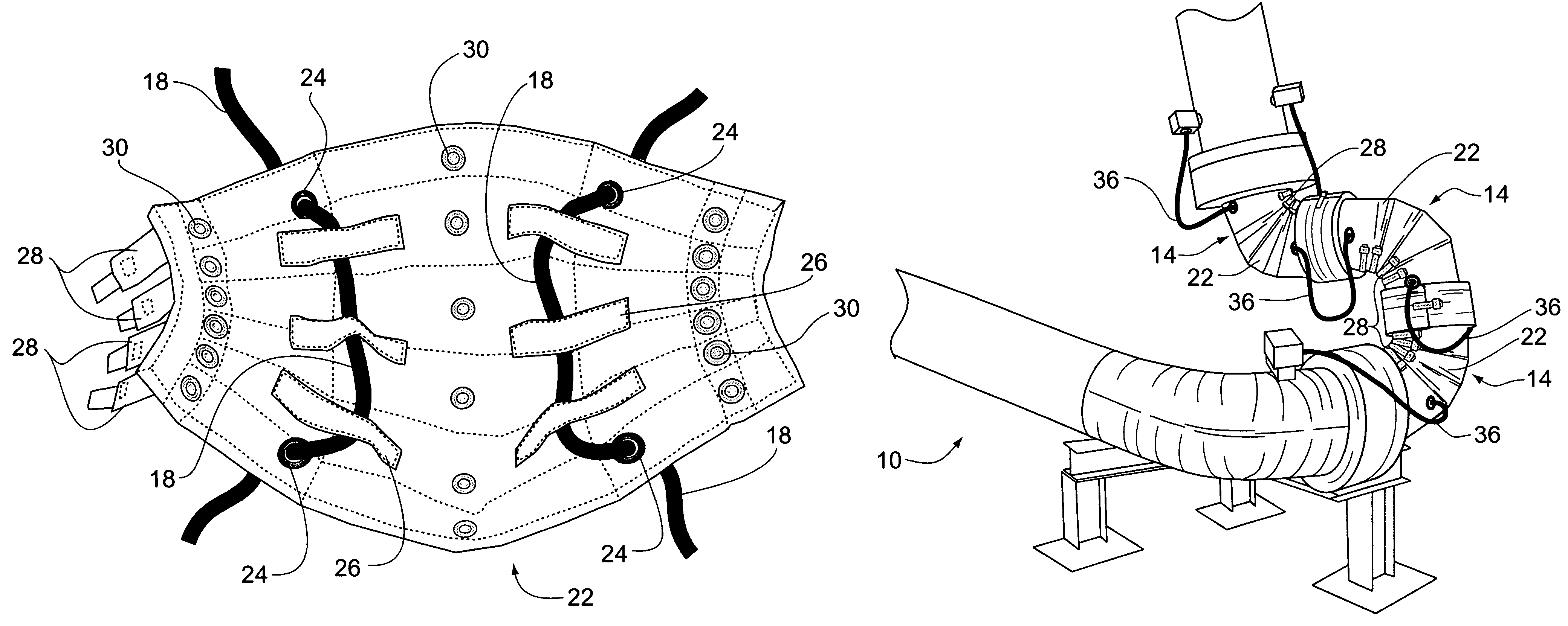
[0009]The present invention provides a structure which applies the heat trace wiring to the joints and elbows of a marine arm while allowing enough flexibility to avoid significant friction in the wiring cable while accommodating movement of the joints. A removable insulation blanket having internal loops for heat cable positioning is wrapped around the joints of the marine arm. The insulating blanket has grommets extending through the blanket which facilitate the entrance and exit of the heat trace cable. The insulating blanket also includes a plurality of loops to support and carry the heat trace wiring thus minimizing significant frictional rubbing of the wiring. The internal loops can also be used to carry and support wiring for the loading arm controls. The insulating jacket is designed to be easily removeable while maintaining the integrity of the wiring cable connections so that sections of the marine arm can be accessed for maintenance without damaging the wiring or insulating blanket.

Problems solved by technology

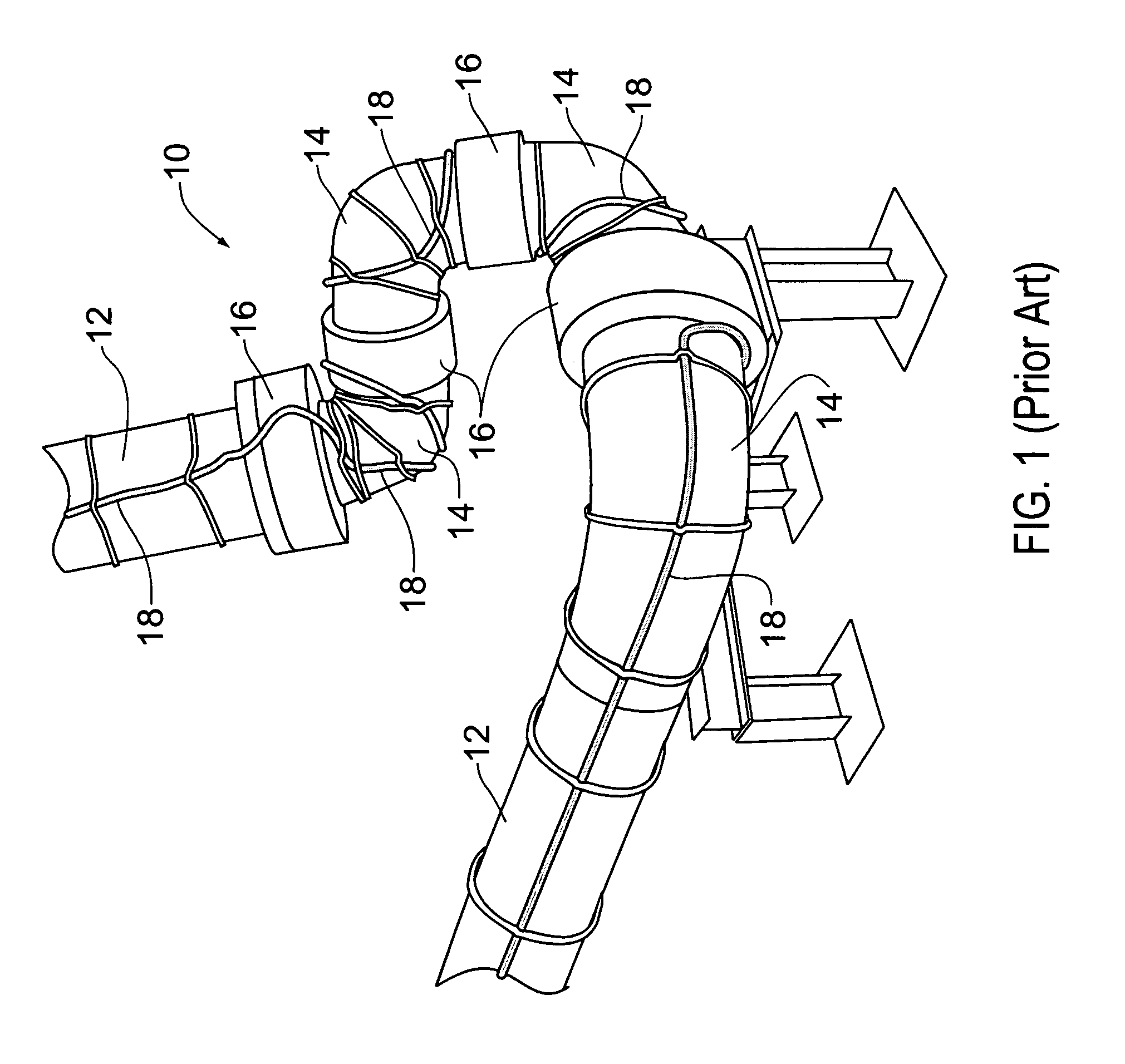
Problems have been encountered in maintaining the integrity of the heat trace wiring, particularly as it is applied to the swivel joints and elbow joints which are flexing and moving as the water level rises and falls.
The heat trace cables have been found to continuously sustain damage from friction and rubbing as the result of the constant movement of the joints.
Other problems are encountered in that the piping and joints require annual maintenance which results in the insulation blanket being removed from the piping.
Removal of the insulation blanket sometimes interferes with the integrity of the heat trace wiring adhered to the piping and causes irreversible damage to the insulation blanket.

Method used


Image

  • Heat trace or control cable support with insulating jackets
  • Heat trace or control cable support with insulating jackets
  • Heat trace or control cable support with insulating jackets

Examples


Embodiment Construction

)

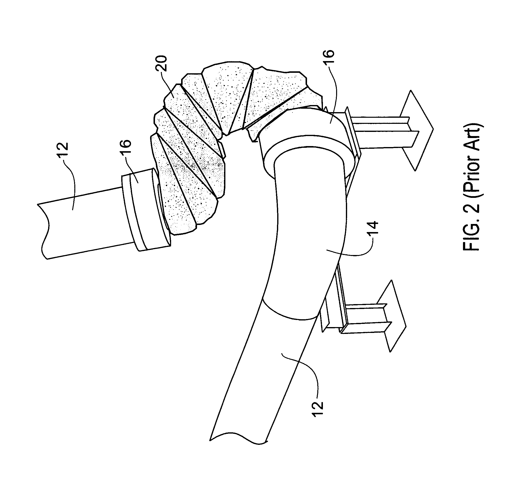
[0016]Referring now to FIG. 1, the prior art system for applying heat trace cable to the swivel joints of marine arm is shown. A typical marine arm 10 generically illustrated in FIG. 1. The marine arm 10 includes sections of straight pipe 12 and curved pipe 14 engaged together at joints 16 that swivel, allowing for relative movement between the various pipes. Heat trace wiring 18 is taped or wired directly to the pipes and joints. It can readily be seen how relative movement between the pipes 12, 14 through the swivel joints 16 could impair the integrity of and damage the heat trace wiring. Further, referring to FIG. 2, insulation blankets 20 were placed around the pipes 12, 14 and heat trace wiring 18 to ensure warmth and proper temperature for the product moving through the pipes 12, 14. General maintenance of the pipes 12, 14 and the heat trace wiring required removal of the insulating blanket, many times destroying the blanket 20 structure.

[0017]The present invention provides a...


PUM


Abstract

A structure is provided that applies support to wiring such as heat trace wiring to the joints and elbows of a marine arm allowing enough flexibility to avoid significant friction in the wiring while accommodating movement of the joints. A removable insulation blanket having internal retention members of wire positioning is wrapped around the joints of the marine arm and the wiring is looped outside the insulation blanket and over the joints to prevent unnecessary friction rubbing of the wiring due to joint movement.

Description

CROSS REFERENCE TO RELATED APPLICATIONS[0001]This application claims the benefit of U.S. provisional patent application Ser. No. 60 / 661,272 filed Mar. 11, 2005.BACKGROUND OF THE INVENTION[0002]Temperature sensitive viscous products, such as asphalt are commonly transported in large quantities by barge. The product is loaded onto a barge from a land based terminal by means of a series of conduits interconnected by swivel joints and elbow joints designed to allow the conduit to be flexible enough to rise and lower as a loading dock rises and lowers based on the level of the river, while at the same time accommodating the piping extending from the terminal located on the shore. The conduit is commonly referred to as a marine arm and is segmented and jointed in such a way to allow for the vertical movement of the floating dock. The products that are either loaded or unloaded from the dock are required to be maintained at higher than ambient temperatures to promote flow of the product. I...

Claims


Application Information

Patent Timeline
IPC IPC(8): H01B7/00
CPCF16L59/026F16L59/027F16L59/18F16L59/22
Inventor PULTER, JEFFREY A.CRAIG, JON
Owner MARATHON PETROLEUM
Learn More