
Apparatus and method for measuring the insulation resistance of a fuel cell system

a fuel cell and apparatus technology, applied in the direction of fuel cells, air-break switch details, propulsion by batteries/cells, etc., to achieve the effect of precise and reliable measurement of insulation resistan

Inactive Publication Date: 2008-01-08
BALLARD POWER SYSTEMS
View PDF6 Cites 12 Cited by
  • Summary
  • Abstract
  • Description
  • Claims
  • Application Information

AI Technical Summary

Benefits of technology

The invention provides an apparatus and method for accurately measuring the insulation resistance of a fuel cell system. The apparatus includes a resistor arrangement, a reference voltage source, a voltage-sensing device, and an evaluation unit. The evaluation unit derives the insulation resistance based on the difference between the voltage between the load-current lines and the ground point while applying different reference voltages. The method involves measuring the voltage while switching between different reference voltages and calculating the insulation resistance based on the measured values. The invention helps to ensure reliable measurements despite fluctuations in the fuel cell voltage.

Problems solved by technology

This solution according to U.S. Pat. No. 5,760,488 is not able to determine an absolute magnitude of the insulation resistance, rather it only allows differentiating between cases that are still considered proper and cases that are no longer considered proper.

Method used


Image

  • Apparatus and method for measuring the insulation resistance of a fuel cell system
  • Apparatus and method for measuring the insulation resistance of a fuel cell system
  • Apparatus and method for measuring the insulation resistance of a fuel cell system

Examples


Embodiment Construction

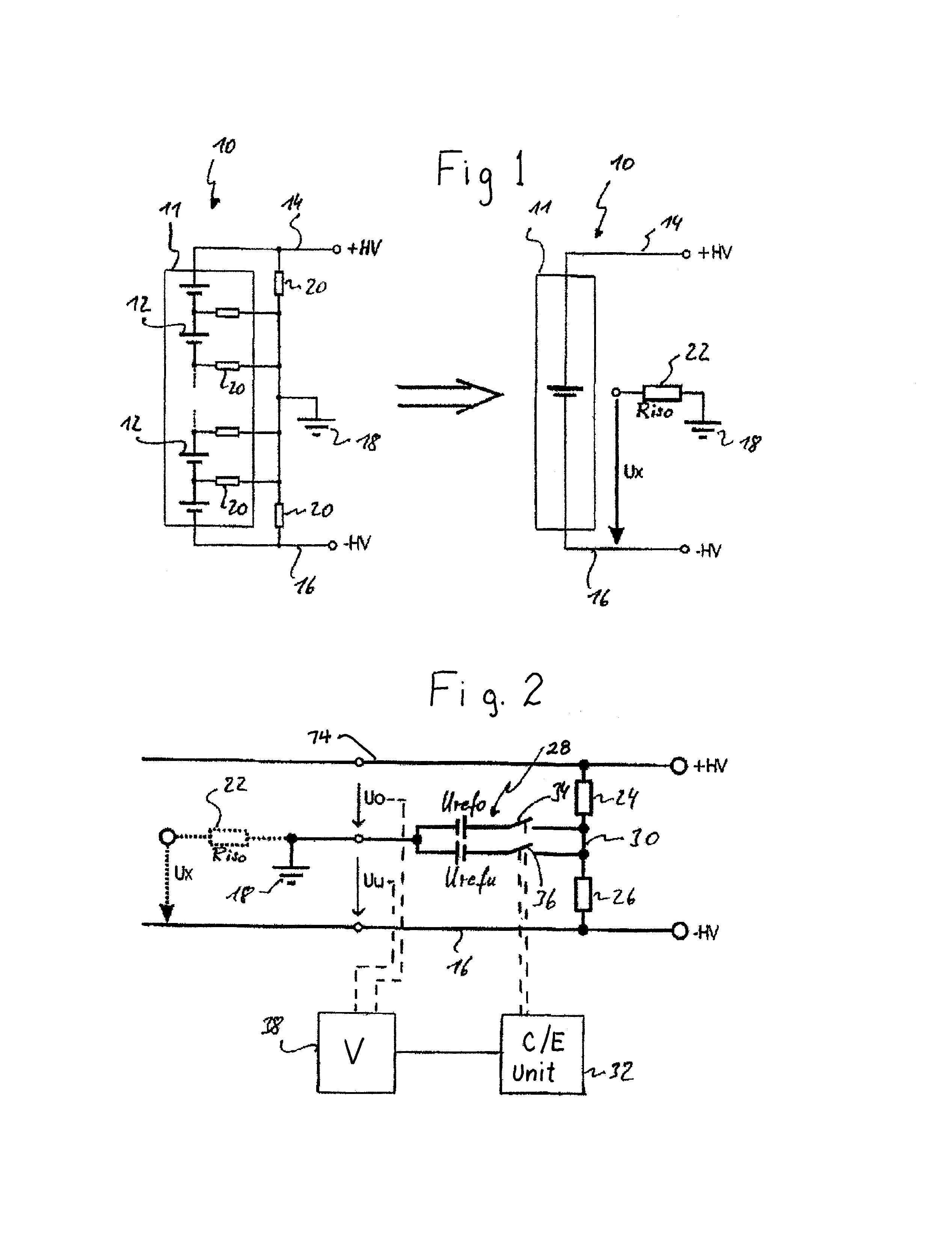
[0037]The left half of FIG. 1 shows a fuel cell system 10 that consists of a multitude of fuel cells 12 that are electrically series-connected and combined to a stack 11. The fuel cell system 10 contains load-current lines 14, 16, between which is in effect the sum voltage of the individual voltages generated by the fuel cells 12. We refer to this sum voltage as fuel cell voltage. In the example shown in FIG. 1, the upper load-current line 14 is at a positive terminal potential +HV, while the lower load-current line 16 is at a negative terminal potential −HV. For applications in the motor vehicle sector, the fuel cell voltage can for example be several hundred volt. But the invention is not at all limited to this order of magnitude of the fuel cell voltage. Any other desired values of the fuel cell voltage are possible.

[0038]The load-current lines 14, 16 are insulated with respect to the ground point (ground system) 18. In this, the potentials of the load-current lines 14, 16 are no...


PUM

PropertyMeasurementUnit
insulation resistanceaaaaaaaaaa
voltageaaaaaaaaaa
timeaaaaaaaaaa

Abstract

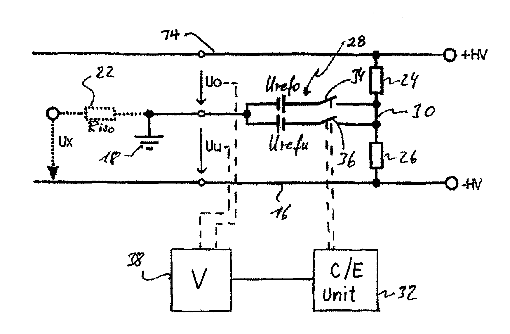
A measuring device to measure the insulation resistance (Riso) of a fuel cell system with respect to an electrical ground point comprises a resistor arrangement—formed by a series connection of reference resistors—between two load-current lines of the fuel cell system as well as one reference voltage source, which is arranged between the ground point and a node between the reference resistors and which is switchable between at least two different reference voltages (Urefo, Urefu). The measuring device further comprises one voltage-sensing device that acquires the voltage (Uo, Uu) between at least one of the load-current lines and the ground point. Connected to the voltage-sensing device is an evaluation unit, which determines the insulation resistance (Riso) on the basis of a first voltage value, which represents a value of the voltage between a first of the load-current lines and the ground point while a first reference voltage (Urefo) of the reference voltage source is applied, and on the basis of a second voltage value, which represents the value of the voltage between the first load-current line and the ground point while a second reference voltage (Urefu) of the reference voltage source is applied.

Description

CROSS-REFERENCE TO RELATED APPLICATION[0001]This application claims the benefit under 35 U.S.C. § 119(e) of U.S. Provisional Patent Application No. 60 / 661,616 filed Mar. 14, 2005; and also claims priority to German Application No. 10 2004 032 230.9, filed Jul. 2, 2004. Both of these applications are incorporated herein by reference in their entireties.BACKGROUND OF THE INVENTION[0002]1. Field of the Invention[0003]The invention pertains to an apparatus and a method for measuring the insulation resistance of a fuel cell system with respect to a point at electrical ground potential.[0004]2. Description of the Related Art[0005]U.S. Pat. No. 5,760,488 describes a so-called IT architecture (IT: isolated terra) for the load circuit of a vehicle-mounted fuel cell system, in which the load-current lines of the fuel cell system are isolated with respect to the vehicle chassis (vehicle ground). The electrical loads that are supplied by the load-current lines possess a low-resistance connectio...

Claims


Application Information

Patent Timeline
Patent Type & Authority Patents(United States)
IPC IPC(8): H01H31/12H01M8/00H02G3/00
CPCG01R27/025G01R31/36H01M8/04649H01M8/04544Y02E60/50B60L2240/547B60L50/71B60L50/72Y02T90/40
Inventor LEITZ, JUERGEN M
Owner BALLARD POWER SYSTEMS
Learn More