High-performance ball socket

Inactive Publication Date: 2008-01-15
ZF FRIEDRICHSHAFEN AG
View PDF15 Cites 3 Cited by
  • Summary
  • Abstract
  • Description
  • Claims
  • Application Information

AI Technical Summary

Benefits of technology

[0006]The object of the present invention is therefore to provide a bearing shell and a ball a

Problems solved by technology

However, the pretension brought about by the spacer nubs on the outer sides of the bearing shell acts on the entire bearing shell or the mounted joint ball and consequently also in areas in which such a pretension counteracts the actual task of the ball and socket joint, or leads to increased wear in certain areas, and thus shortens the service life of the ball and socket joint.
However, the bearing shell must be lengthened in this embodiment to mount the joint ball in the bearing shell, which is equivalent to a great mounting effort as well as a high load on the mater

Method used


Image

  • High-performance ball socket
  • High-performance ball socket
  • High-performance ball socket

Examples


Embodiment Construction

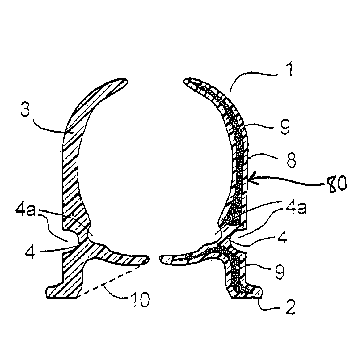
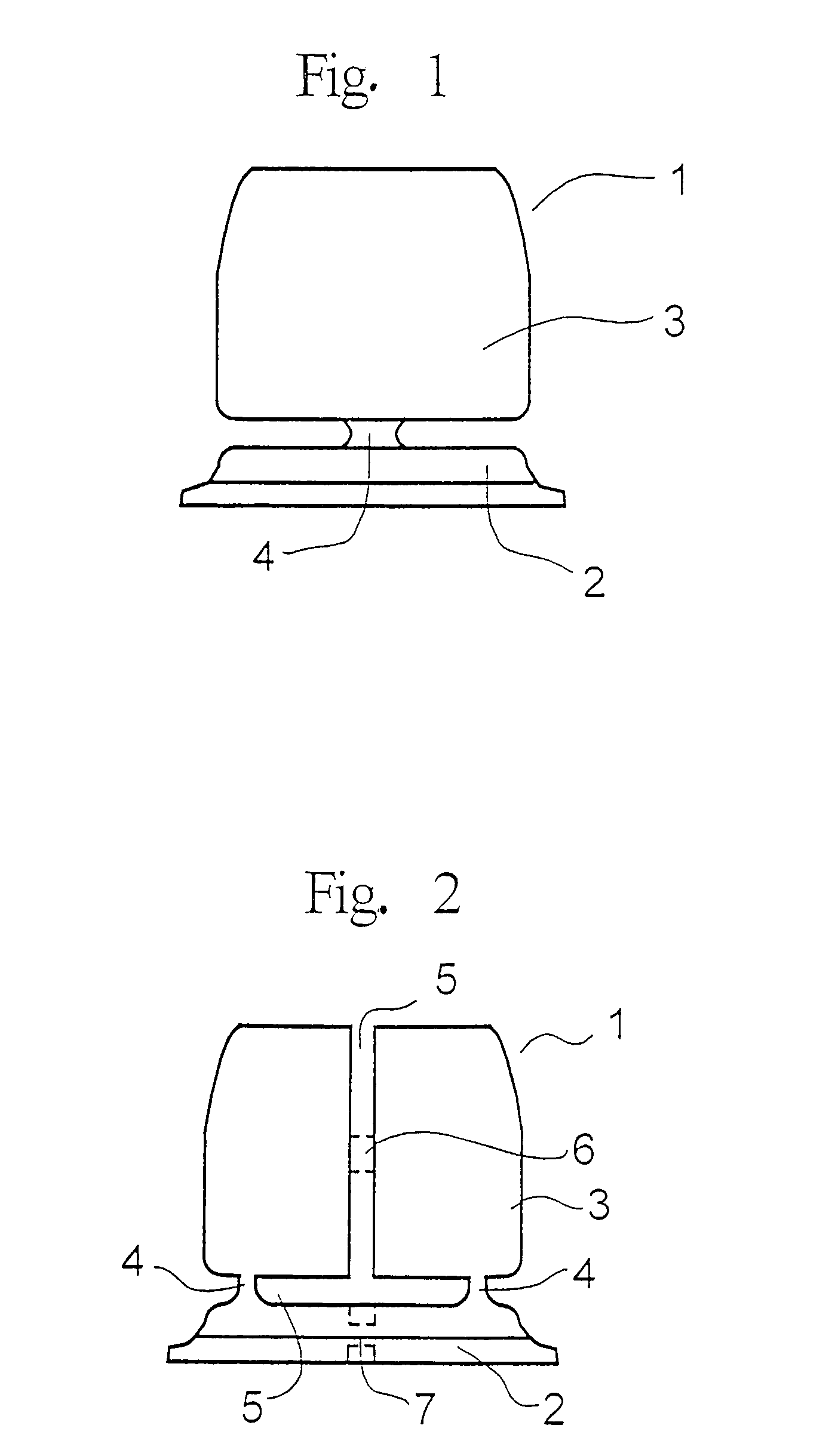
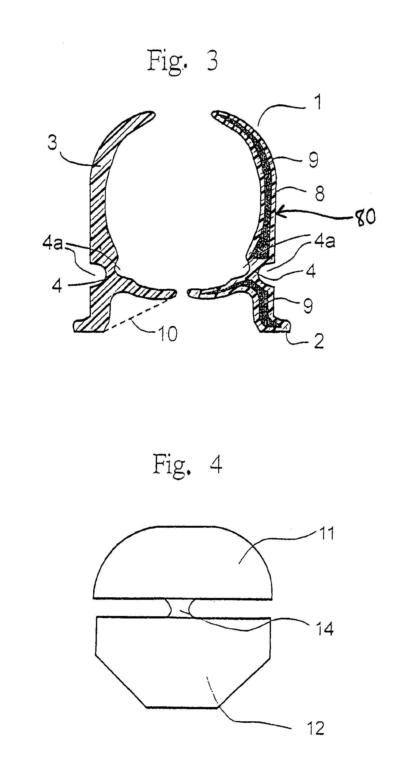
[0023]Referring to the drawings, FIGS. 1 through 3 show a bearing shell 1 of a ball and socket joint loaded mainly radially. The bearing shell has a one-part design and has a basic body 2, with which a bearing shell part 3 comprising a joint ball receiving part is made integrally in one piece. To simplify the mounting, the bearing shell 1 is provided with elastic webs 4 and slots 5, which enable the bearing shell 1 to expand elastically during the mounting operation. Weakening of the plastic, which is otherwise common, and which may lead to rupture of the bearing shell due to the strain of the plastic during the mounting operation, is counteracted by the elastic expansion already during the mounting operation.

[0024]The bearing shell according to FIG. 1 is intended mainly for radially loaded ball and socket joints. The elastic web 4 is designed such that, combined with a circular slot 5, the bearing shell can expand elastically without the application of any great force during the mo...


PUM


Abstract

A bearing shell for a ball and socket joint made of plastic as well as the ball and socket joint per se, wherein the bearing shell has first areas, which are subject to higher mechanical loads than the other areas of the bearing shell, wherein the material of the bearing shell forming the first areas is formed from a reinforced plastic, and the other areas are made of a less reinforced or unreinforced plastic.

Description

CROSS REFERENCE TO RELATED APPLICATION[0001]This is a continuation of and claims the benefit (35 U.S.C. §120 and 365(c)) of copending International Application PCT / DE 2003 / 002387 of 16 Jul. 2003, which designated inter alia the United States and which claims the priority of German Application DE 102 33 489.7 of 24 Jul. 2002. The entire contents of each application is hereby incorporated by reference in its entirety.FIELD OF THE INVENTION[0002]The present invention pertains to a bearing shell made of plastic for a ball and socket joint, especially for motor vehicles as well as to the ball and socket joint per se.BACKGROUND OF THE INVENTION[0003]A bearing shell of this class for ball and socket joints, especially for motor vehicles, is known from DE 29722507 U1. DE 29722507 U1 discloses a bearing shell, which has slots for elastic deflection during the mounting of a joint ball in the bearing shell, the slots extend essentially in the direction of the central axis of the bearing shell....

Claims


Application Information

Patent Timeline
IPC IPC(8): F16C11/00F16C11/06F16C11/08
CPCF16C11/0633F16C11/0638Y10T403/32786Y10T403/32795Y10T403/32721Y10T403/32803Y10T403/32737F16C11/06
Inventor BUDDE, FRANK
Owner ZF FRIEDRICHSHAFEN AG
Why Eureka
Try Eureka