
Air-isolator fume hood

a fume hood and air isolation technology, applied in the field of fume hoods, can solve the problems of harming on-site workers, improper positioning of suction, and the use of hoods only in harmful or highly dangerous working environments, so as to save energy, quickly exhaust pernicious gases, and save energy

Inactive Publication Date: 2008-01-15
INST OCCUPATIONAL SAFETY & HEALTH COUNCIL LABOR AFFAIRS EXECUTIVE YUAN
View PDF5 Cites 41 Cited by
  • Summary
  • Abstract
  • Description
  • Claims
  • Application Information

AI Technical Summary

Benefits of technology

[0014]Therefore, the main purpose of the present invention is to dynamically combine a sash with a fume hood, where the sash has an air pipe and the fume hood has an exhaust outlet deposed at the front rim of the bottom surface with a suction slot corresponding to the air pipe so that an efficient local air-suction near a contaminant source is obtained to exhaust pernicious gases while saving energy.
[0015]Another purpose of the present invention is to depose a screen on the top of the fume hood to obtain a mechanism of air suction together with air supply to quickly exhaust pernicious gases while saving energy.
[0016]To achieve the above purposes, the present invention is an air-isolator fume hood, comprising a hood, a sash, an exhaust outlet, a blower and a screen. Therein, the hood has a containing space to contain pernicious gases to be exhausted, and accessible spaces at the top surface and the side surface; the sash having an air pipe is dynamically combined with the hood at a side with the opening height controlled; the exhaust outlet with a suction slot corresponding to the air pipe is deposed at the front bottom rim of the hood; the blower is deposed at an exit end of the exhaust outlet for exhausting pernicious gases; and, the screen is deposed on the top of the hood to supply air. Accordingly, an air-isolator fume hood is obtained with a mechanism of air suction and air supply to save energy while locally exhausting pernicious gases near a contaminant source; and an air curtain is obtained to efficiently prevent contaminant from leakage.

Problems solved by technology

But the close-type hood is totally closed and so may do harms to the on-site workers.
So, this kind of hood is used only in harmful or highly dangerous working environments.
1. Lacking most appropriate design: such as being short in air suction, improperly positioning suction slot, inappropriately locating air supply, unevenly distributing air velocity at an opening, unfavorably designing edges at the opening, etc.
2. Not operating under the best situation: such as too much pernicious objects released, inner pernicious objects rapidly escaping toward the opening, too big movement of operation from the inside to the outside, over wide-opened sliding door, air suction lack of examination when operating, etc.
3. Maintaining improperly: such as breakage of the booth wall or the pipe, malfunction or disability of the exhausting device, etc.
In addition, because the circulations stay close to the sash 85, the harmful output may escape outside following the stirring of the circulations by mixing into them.
The problems with the above fume hoods are owing to the lack of considering the flow field structure of CFD.
So, the refinements to the structure of the fume hood according to the prior art, such as the refinements to baffle, blower, sash and wall, do not benefit much to prevent circulations in the flow fields or to prevent the harmful output from leakage.
These refinements may cost a lot yet the results are much in doubt.
So, the prior arts do not fulfill users' requests on actual use.

Method used


Image

  • Air-isolator fume hood
  • Air-isolator fume hood
  • Air-isolator fume hood

Examples


Embodiment Construction

[0025]The following description(s) of the preferred embodiment(s) is / are provided to understand the features and the structures of the present invention.

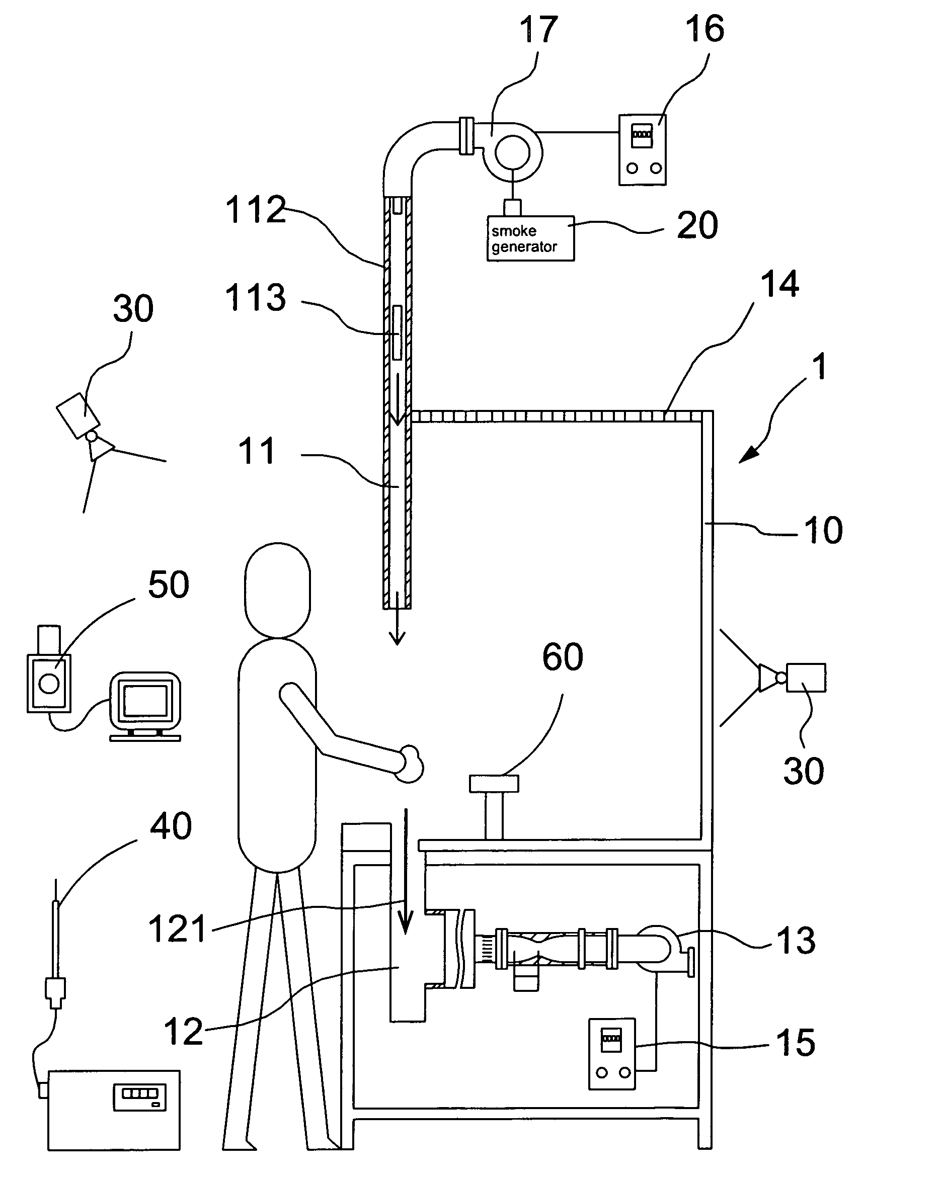
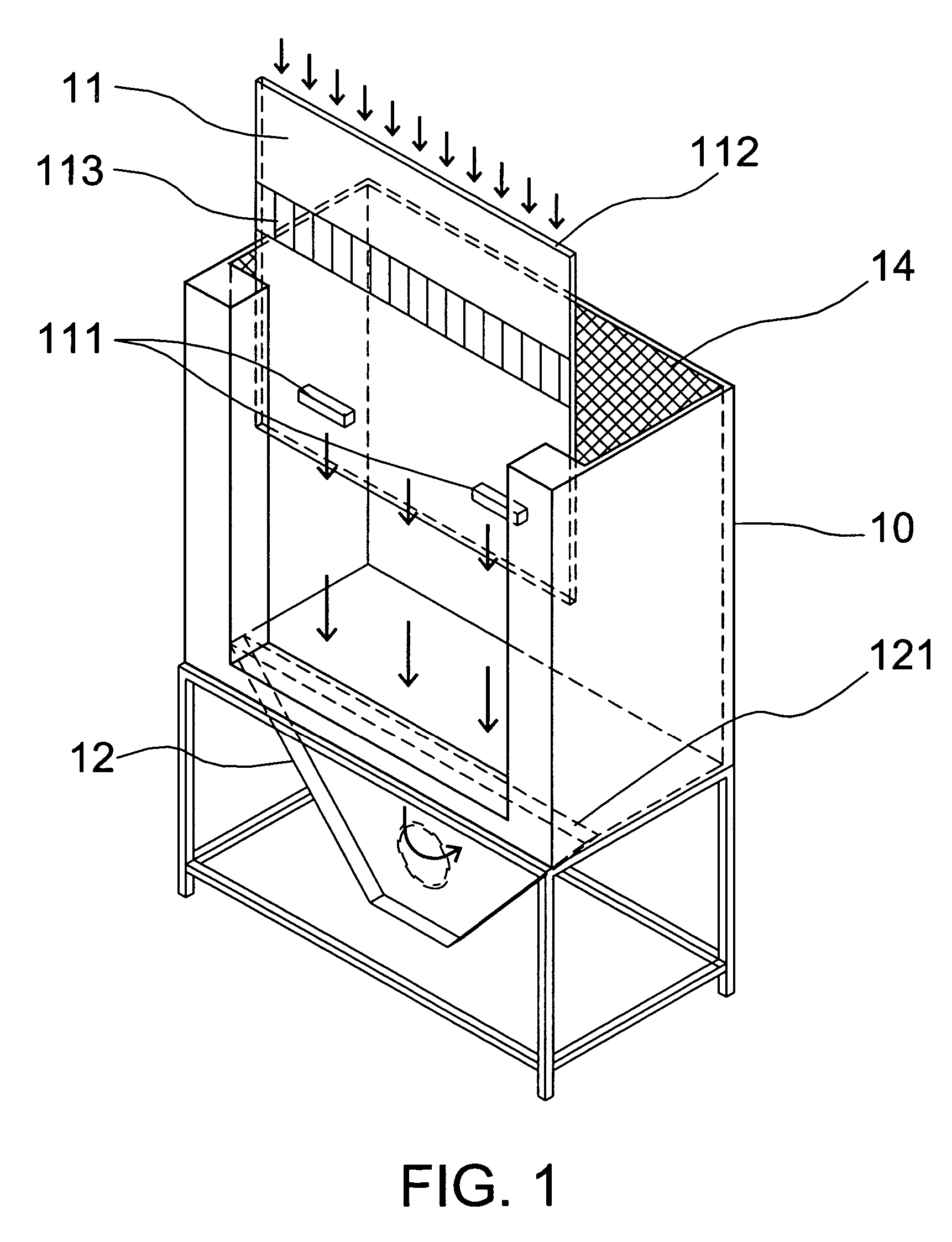
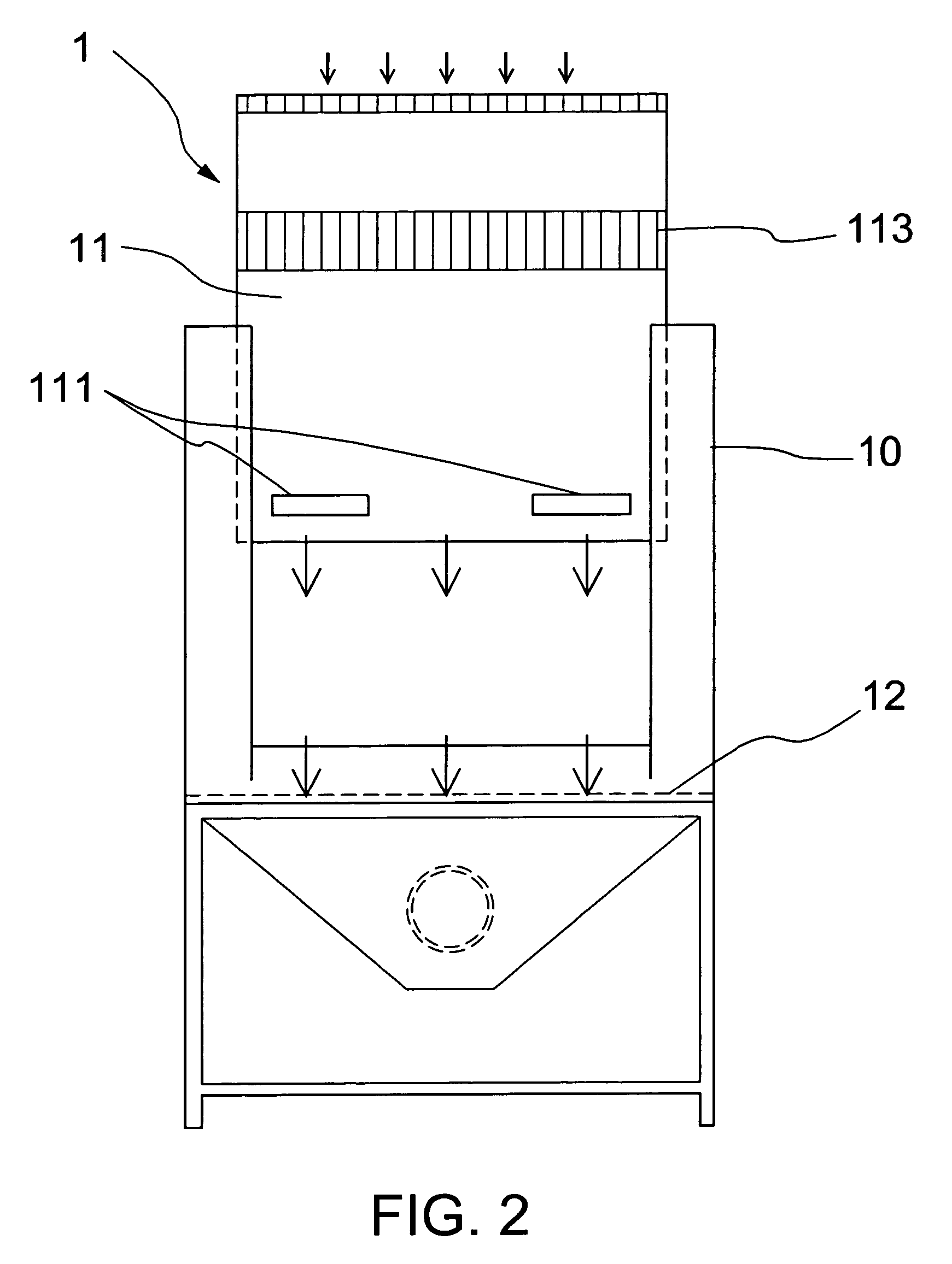
[0026]Please refer to FIG. 1 through FIG. 4, which are a perspective view, a front view and a cross-sectional view showing a preferred embodiment, and a view showing a status of use of the preferred embodiment, according to the present invention. As shown in the figures, the present invention is an air-isolator fume hood, which comprises:

[0027](a) a hood 10 having a containing space to contain pernicious gases to be exhausted, the hood having accessible spaces at the top surface and at a side surface;

[0028](b) a sash 11 dynamically combined with the hood 10 at the side surface, the sash 11 having a handle 111 for moving the sash 11 to control the opening height of the sash 11, the sash 11 having a maximum opening height (HMax) of 60 cm (centimeter), the sash 11 having an air pipe 112, a process of supplying air by the sash 11 compri...


PUM


Abstract

The present invention is a fume hood capable of exhausting contaminant, having an air pipe in a sash and a suction slot corresponding to the air pipe deposed at the front rim of the bottom surface to obtain an air curtain, where contaminant is efficiently prevented from leakage and energy is saved.

Description

FIELD OF THE INVENTION[0001]The present invention relates to a fume hood; more particularly, relates to dynamically combining a sash having an air pipe, and an exhaust outlet having a suction slot, corresponding to the air pipe, deposed at the front rim of the bottom surface, where, by deposing a screen on top of the fume hood, a physical mechanism of air exhaust together with air supply is obtained; and an air curtain is obtained between the air pipe and the suction slot to prevent contaminant from leakage while exhausting air locally near the contaminant source, so that energy can be saved and the contaminant can be exhausted and prevented from leakage, which can be applied in some processes for producing semiconductors (such as photoresist etching, crystal furnace cleansing, etc.) or be applied in a laboratory or a similar construction.DESCRIPTION OF THE RELATED ARTS[0002]A hood is a main part for a local exhauster, which mainly exhausts contaminant gases into a local exhausting ...

Claims


Application Information

Patent Timeline
Patent Type & Authority Patents(United States)
IPC IPC(8): B08B15/02
CPCB08B15/023B25H1/20
Inventor HUANG, RONG FUNGCHEN, YU-KANGSHIH, TUNG-SHENGCHANG, CHENG-PINGCHEN, CHUN-WANWU, YI-TACHEN, HUNG-TA
Owner INST OCCUPATIONAL SAFETY & HEALTH COUNCIL LABOR AFFAIRS EXECUTIVE YUAN
Learn More