

Bicycle derailleur
a derailleur and bicycle technology, applied in mechanical equipment, transportation and packaging, gearing, etc., can solve the problems of cumbersome re-detailing procedure and tremendous time loss, and achieve the effect of easy chain low cost and easy return to tension pulley
- Summary
- Abstract
- Description
- Claims
- Application Information
AI Technical Summary
Benefits of technology
Problems solved by technology
Method used
Image

Examples
Embodiment Construction
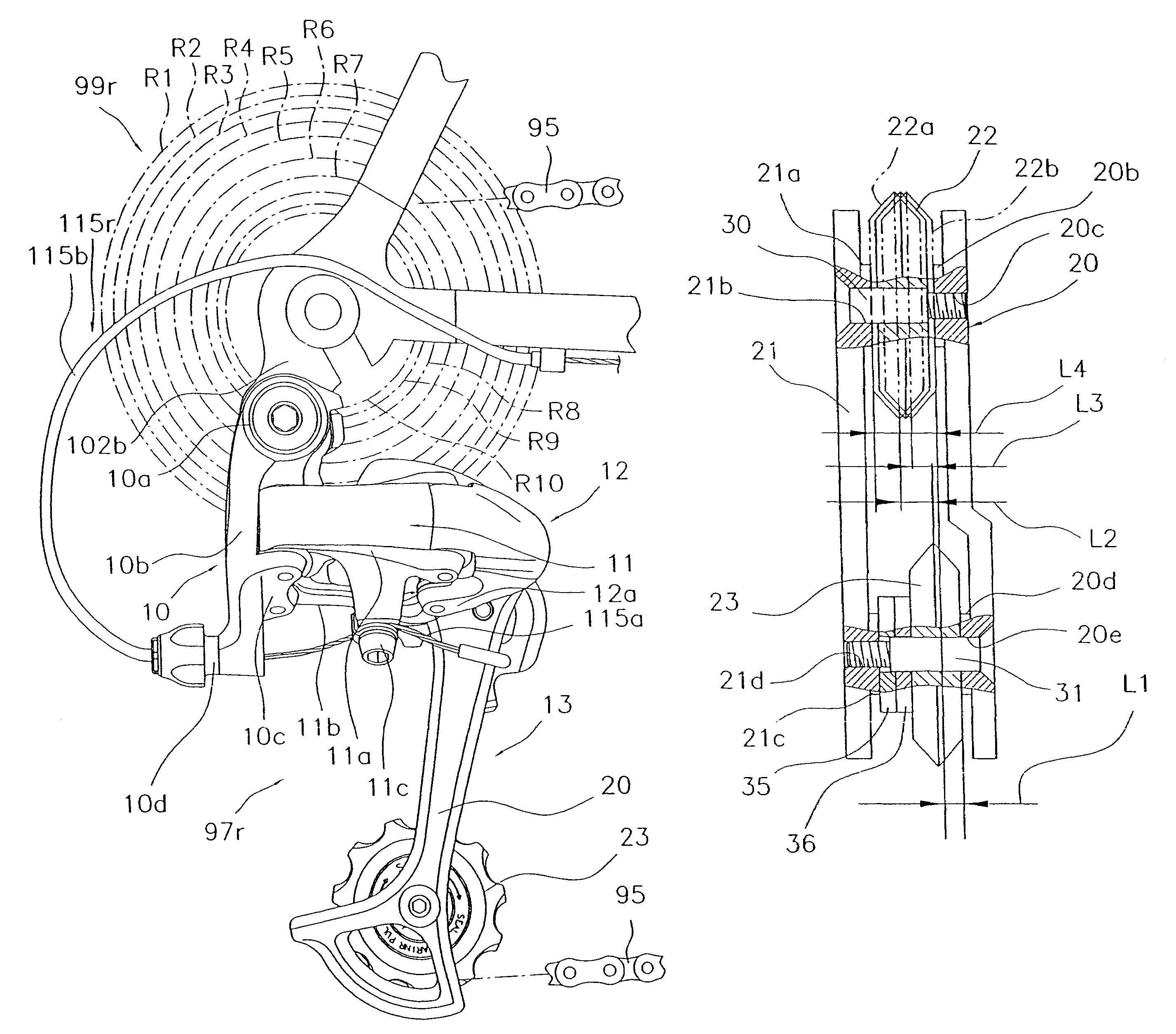
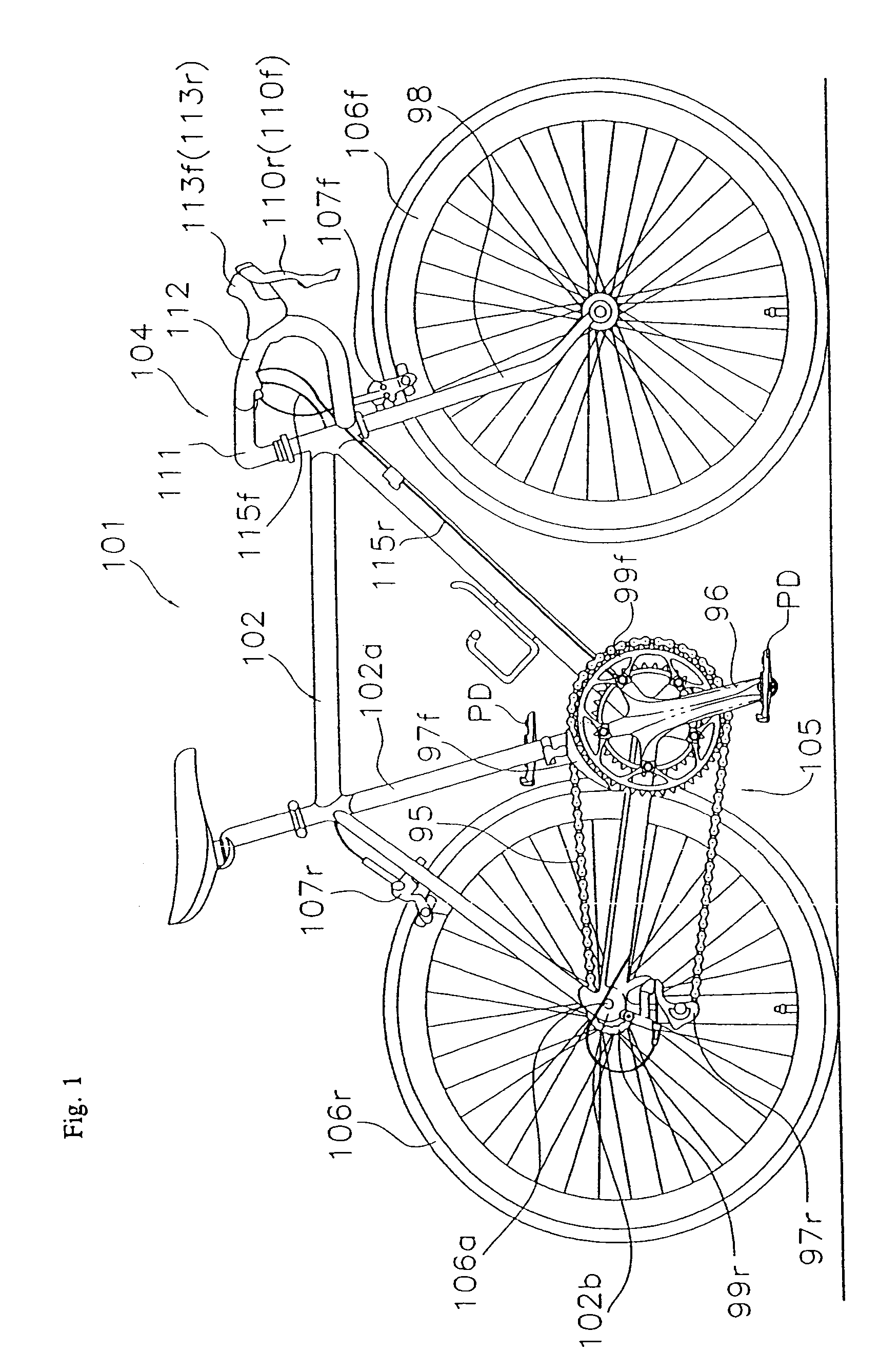
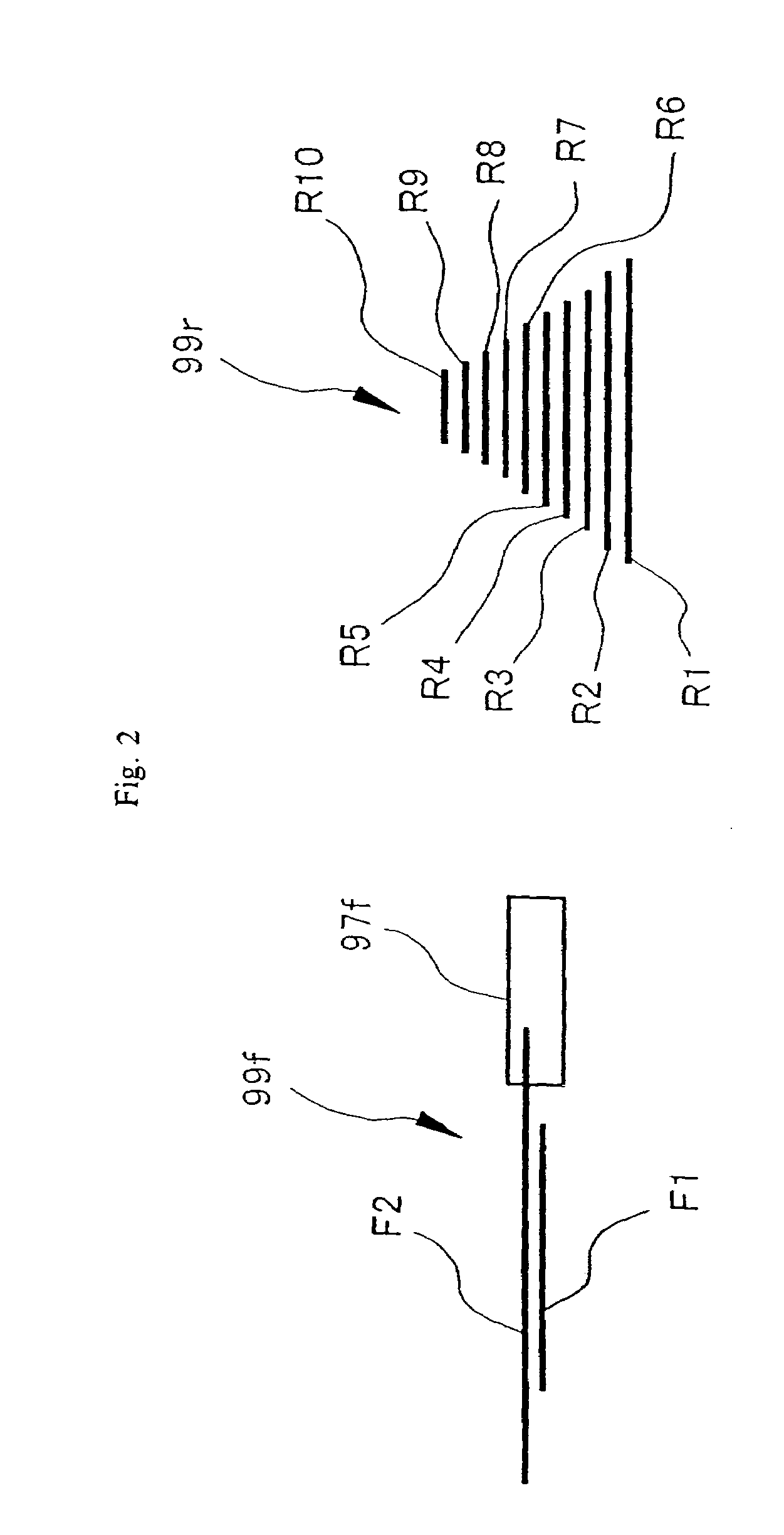
[0007]In accordance with a preferred embodiment of the present invention, a Bicycle rear derailleur is provided which is mounted onto a bicycle frame in order to selectively derail the chain resting upon any of a multiple number of sprockets mounted onto a rear hub axis, and which is equipped with a base component, a link mechanism, a movable component, an outer plate, an inner plate, a guide pulley, and a tension pulley. The base component is mounted onto the frame. One end of the link mechanism is mounted onto the base component. The movable component is mounted onto the other end of the link mechanism, and can be relatively displaced from the base component. The outer plate is mounted unto the movable component so as to undulate like a see-saw. The inner plate is installed so as to face the outer plate. The guide pulley is mounted onto a portion on one edge of the plates, between the plates, so as to freely rotate and freely move in the axial direction, and can be engaged by mean...
PUM
 Abstract
Description
Claims
Application Information