Structure of clinch portion of mounting cup

a technology of mounting cup and clinch, which is applied in the direction of caps, liquid handling, transportation and packaging, etc., can solve the problems of sealing defect or exterior defect, and achieve the effect of preventing gasket extrusion, preventing gasket extrusion, and easy insertion

Active Publication Date: 2013-08-13
TOYO SEIKAN KAISHA LTD +1
View PDF12 Cites 3 Cited by
  • Summary
  • Abstract
  • Description
  • Claims
  • Application Information

AI Technical Summary

Benefits of technology

[0020]According to the invention described in claim 1, the inner plane of the curl portion is constituted of a plurality of curved planes having different radii, and a space the gasket can enter is prepared between the virtual curved plane and the curved plane in the inner portion and / or outer portion. It is therefore possible to accommodate the gasket and prevent extrusion of the gasket.
[0021]According to the invention described in claim 2, the radius of the virtual curved plane is set shorter than the radius of the curved plane of the inner portion and / or outer portion so that the space for accommodating the gasket can be formed easily.
[0022]According to the invention described in claim 3, a radius of the curved plane in the outer portion is set different from a radius of the curved plane in the inner portion so that the size and shape of the space for accommodating the gasket become different between the inner and outer portions. It is therefore possible to reliably prevent extrusion of the gasket.
[0023]According to the invention described in claim 4, an outer diameter of an upper portion of the outer circumferential wall continuous with the curl portion of the mounting cup is set larger than an outer diameter of a lower portion continuous with the upper portion. When the gasket is inserted and fitted upwards along the outer circumferential wall having a smaller outer diameter, the gasket can be inserted easily and workability is improved since there is a sufficiently marginal clearance.
[0024]Since the upper portion of the outer circumferential wall has a larger diameter, a clearance from the inner circumferential plane of the gasket having an annular ring shape is very narrow so that the position of the gasket in the curl portion can be determined precisely.
[0025]According to the present invention, the main portion of the inner plane of the curl portion is constituted of a curved plane corresponding to the shape of the can bead. A compression force applied to the gasket by the can bead during a clinching process can be distributed uniformly in the gasket.

Problems solved by technology

In this case, an extruded portion 110 or a dropout portion is formed, resulting in an exterior defect or a seal defect.

Method used


Image

  • Structure of clinch portion of mounting cup
  • Structure of clinch portion of mounting cup
  • Structure of clinch portion of mounting cup

Examples


first embodiment

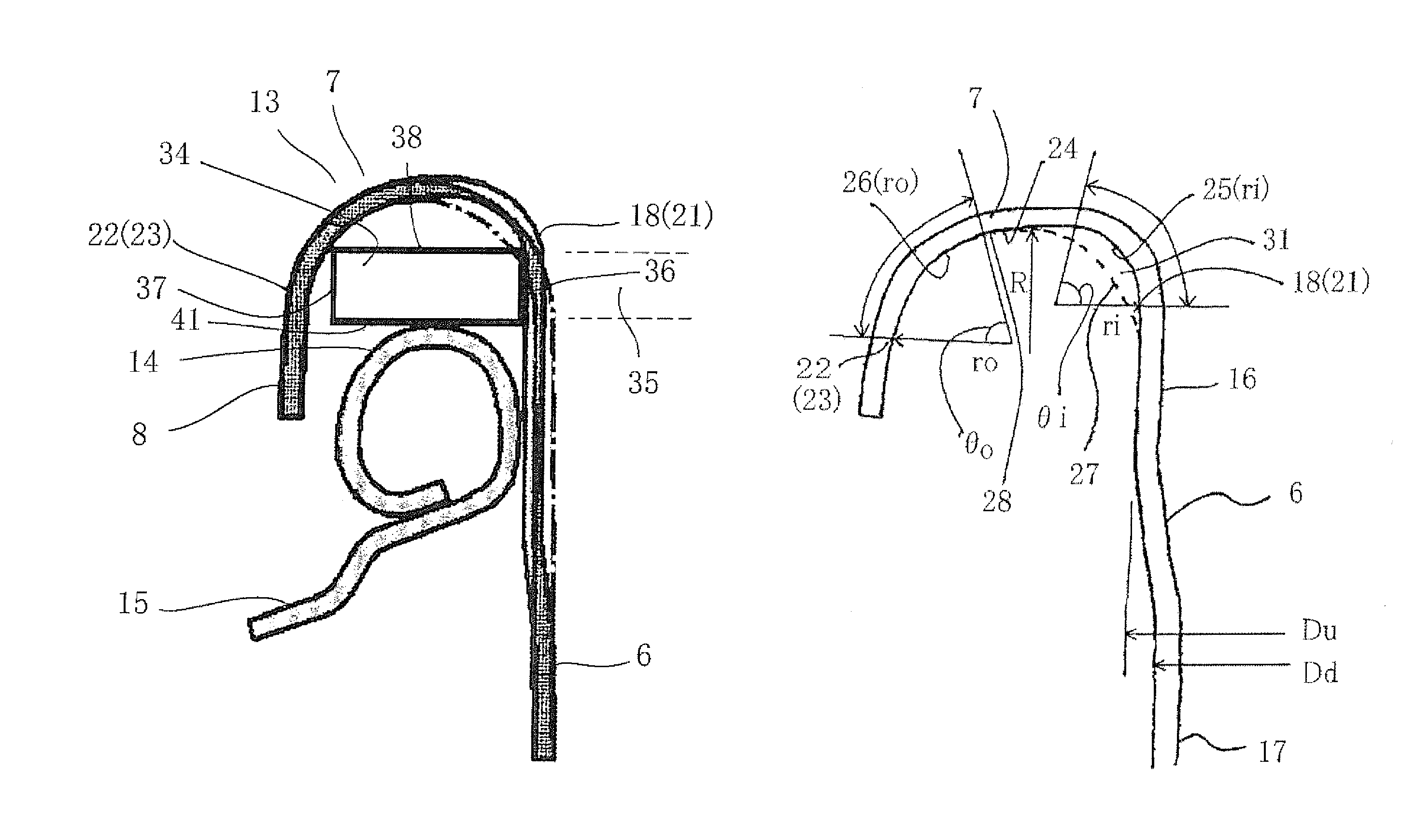
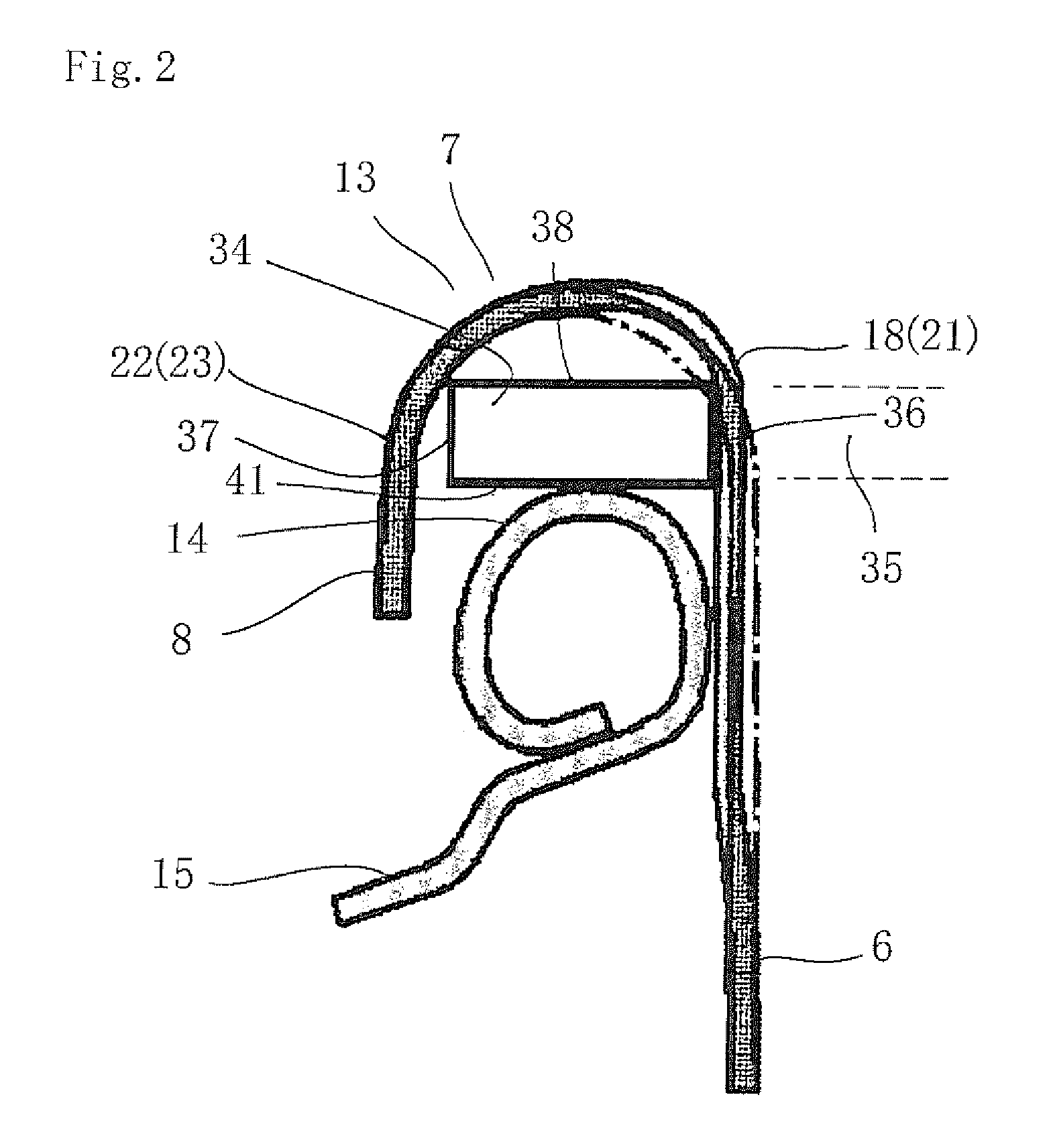
[0058]A mounting cup having the shape shown in FIG. 2 was manufactured and a gasket and a valve stem were mounted. The mounting cup was made of a tinned plate having a thickness of 0.3 mm, and the sizes were set as follows: a radius ri of the curved plane in the inner portion was 1.0 mm; a radius ro of the curved plane in the outer portion was 1.6 mm; a diameter Du of the upper portion of the outer circumferential wall was 25.3 mm, a diameter Dd of the lower portion of the outer circumferential wall was 25.0 mm.

[0059]Propellant was filled in an aerosol can main body having a can bead inner diameter of 1 inch (25.4 mm), and the manufactured mounting cup was clinched to the aerosol can and sealed. In this case, in order to make it easy to extrude a gasket, a clinch load larger than an ordinary load was applied. There was no leak of propellant from the clinch portion. Extrusion of the gasket was evaluated in three degrees, large, middle and small, by visual observation in a lateral dir...


PUM


Abstract

The structure of a clinch portion of a mounting cup is provided which can retain a gasket. The clinch portion includes a curl portion continuous with an upper end of an outer circumferential wall at an inner circumferential edge of the curl portion, and a curl skirt portion having an upper end continuous with an outer circumferential edge of the curl portion. The curl portion is made of a plurality of curved planes having different radii extending from the inner circumferential edge to outer circumferential edge. A space a portion of the gasket can enter is formed between a virtual curved plane with a radius constituting the inner plane of the curl portion and an inner curved plane or an outer curved plane, or between the virtual curved plane and both the inner and outer curved planes.

Description

CROSS-REFERENCE TO RELATED APPLICATIONS[0001]This application is a 371 of PCT / JP2009 / 058111 filed Apr. 17, 2009, which claims the benefit of Japanese Patent Application No. 2008-115234 filed Apr. 25, 2008, the contents of each of which are incorporated herein by reference.TECHNICAL FIELD[0002]The present invention relates to the structure of a clinch portion of a mounting cup of an aerosol container, the clinch portion clinching a can bead with a gasket being held therebetween.DESCRIPTION OF RELATED ART[0003]An aerosol container contains the liquid contents in a can tube in a pressured state, and the liquid contents are ejected from a nozzle as a valve stem mounted on a mounting cup is depressed to open a valve.[0004]A mounting cup in a valve mounting state is clinched to a can bead at the apex of a can tube, to seal the mounting cup and can bead with a gasket. Namely, as shown in FIG. 5, a conventional mounting cup 101 is clinched and fixed to a can bead 14 of a container main body...

Claims


Application Information

Patent Timeline
Patent Type & Authority Patents(United States)
IPC IPC(8): B65D6/28
CPCB65D83/38
Inventor TASAKI, MINORUMORISHITA, SUNAOKINOSHITA, KOUJIKUMAI, TAKAHO
Owner TOYO SEIKAN KAISHA LTD
Why Eureka
Try Eureka