Premixing Apparatus

a technology of pre-mixing apparatus and pre-mixing liquid, which is applied in the direction of burners, combustion types, fuel supply regulation, etc., can solve the problems of increasing the amount of fuel gas supply, unable to supply air or fuel gas depending on the required fuel amount, and unable to meet the requirements of the required combustion amount, etc., to achieve the effect of reducing wind nois

Active Publication Date: 2017-09-28
RINNAI CORP
View PDF2 Cites 2 Cited by
  • Summary
  • Abstract
  • Description
  • Claims
  • Application Information

AI Technical Summary

Benefits of technology

[0008]In view of the above point, this invention has a problem of providing a premixing apparatus in which, irrespective of the fact that the air resistance changeover means is constituted by a butterfly valve, the wind noise can be reduced.

Problems solved by technology

However, in case the required combustion amount falls below a predetermined value and, as a result, the fan revolution has fallen below a lower limit revolution below which the proportional characteristics of the air supply volume cannot be maintained, or in case the electric current to the proportional valve (electric current to be charged to the proportional valve) has fallen below a lower limit electric current below which the proportional characteristics of the gas supply amount cannot be maintained, the air or fuel gas in amount depending on the required combustion amount can no longer be supplied.
Also in this arrangement, if the fan revolution has fallen below a lower limit revolution at which the proportional characteristics of the air supply amount can be maintained, the air or fuel gas depending on the required fuel amount can no longer be supplied.
Further, only by increasing the ventilation resistance in the air supply passage, the amount of fuel gas supply will exceed the amount corresponding to the required combustion amount due to an increase in the negative pressure in the air supply passage.
As a result, there will be generated turbulence in the air flow, whereby wind noise is generated at the annular clearance, giving rise to noises.

Method used


Image

  • Premixing Apparatus
  • Premixing Apparatus
  • Premixing Apparatus

Examples


Embodiment Construction

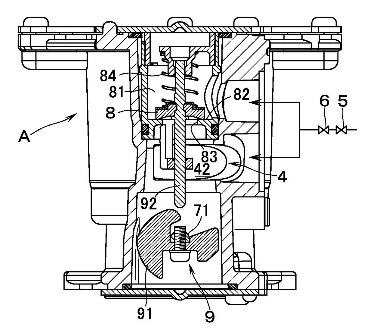
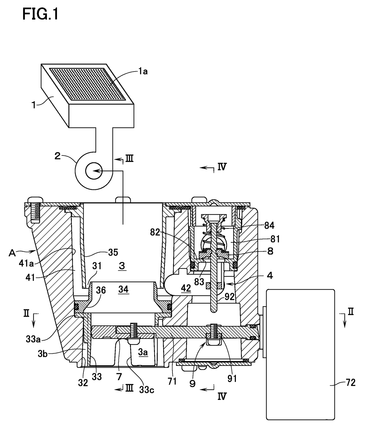
[0018]With reference to FIG. 1, reference numeral 1 denotes a burner which is made up of a totally aerated combustion type burner (also called “all primary air burner”) and the like having a combustion surface 1a in which the air-fuel mixture is ejected and combusted. The burner 1 has connected thereto a fan 2 and, by means of a premixing apparatus A according to an embodiment of this invention, the fuel gas is mixed with air so that air-fuel mixture is supplied to the burner 1 via the fan 2.

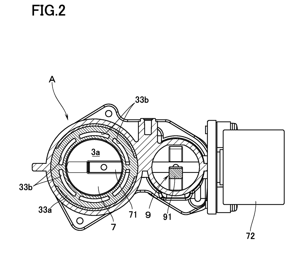
[0019]The premixing apparatus A is provided with an air supply passage 3 on the upstream side of the fan 2, and a gas supply passage 4 to supply a fuel gas. In the upstream section of the gas supply passage 4, there are interposed an on-off valve 5, and a flow control valve 6 which is made up of a proportional valve or a zero governor as shown in FIG. 4. Further, the downstream end of the gas supply passage 4 is connected to a gas suction section 31 which is disposed in the air supply passage 3....


PUM


Abstract

A premixing apparatus in which a downstream end of a gas supply passage having interposed therein a flow control valve is connected to a gas suction section disposed in an air supply passage on an upstream side of a fan. The premixing apparatus has: a butterfly valve as an air resistance changeover device for changing over, between high and low, a ventilation resistance in that section of the air supply passage which is on the upstream side of the gas suction section; and a gas resistance changeover device for changing over, between high and low, a ventilation resistance in that section of the gas supply passage which is on the downstream side of the flow control valve. Wind noises at the time of closing the butterfly valve can be prevented. For that purpose, in that section of the air supply passage which is on the upstream side of the gas suction section, an inner tube containing therein the butterfly valve is disposed while leaving a clearance to an inner circumferential wall surface of the air supply passage. A subsidiary passage which is parallel with a main passage inside the inner tube is constituted by the clearance between the inner circumferential wall surface of the air supply passage and an outer peripheral surface of the inner tube.

Description

TECHNICAL FIELD[0001]The present invention relates to a premixing apparatus for mixing fuel gas with air to supply thus obtained air-fuel mixture, through a fan, to a burner.BACKGROUND ART[0002]As this kind of premixing apparatus, the following is known in JP-A-2015-230113; that is, a downstream end of that gas supply passage for supplying fuel gas which has interposed therein a flow control valve, is connected to a gas suction section disposed in an air supply passage on an upstream side of the fan. The premixing apparatus comprises: an air resistance changeover means for changing over, between high and low, a ventilation resistance in that section of the air supply passage which is on an upstream side of the gas suction section; and a gas resistance changeover means for changing over, between high and low, a ventilation resistance in that section of the gas supply passage which is on the downstream side of the flow control valve.[0003]By the way, in case a proportional valve is us...

Claims


Application Information

Patent Timeline
Patent Type & Authority Applications(United States)
IPC IPC(8): F23D14/06
CPCF23D14/06F23K5/002F23N1/027F23D14/62
Inventor SHIMAZU, TOMOYUKIMIYATA, MITSURU
Owner RINNAI CORP
Why Eureka
Try Eureka