Wideband antenna device with extended ground plane in a portable device

a wideband antenna and portable device technology, applied in the direction of antenna details, electrically long antennas, antennas, etc., can solve the problems of unsuitable use in a small portable device, low efficiency of small antennas and big antennas, and achieve the effect of improving esd robustness and good performan

Inactive Publication Date: 2008-01-15
SONY CORP
View PDF16 Cites 7 Cited by
  • Summary
  • Abstract
  • Description
  • Claims
  • Application Information

AI Technical Summary

Benefits of technology

[0009]Therefore, the object of the present invention is to provide an antenna device, which is sufficiently small to fit in small portable devices and which has efficiency and bandwidth to meet requirements of known and future communications protocols.
[0018]Additionally, the antenna device may be provided with a bezel, which is connected to the PCB, for fending off ESD (Electrostatic Discharges) discharges. The bezel extends from the third side of the PCB towards the fourth side of the PCB. Also, to improve ESD robustness, the antenna device may be provided with bezel flanges connected to the ground plane of the PCB, which extends along the third and fourth sides of said PCB.
[0019]A further object of the invention is to provide an PCB comprising an antenna device, which is sufficiently small to fit in small portable devices, and which has good performance to meet requirements of communications protocols.
[0021]Finally, it is an object of the invention to provide a portable communication device having an antenna with good performance and being sufficiently small to fit into a small portable device. The efficiency of the antenna device should be high to keep the power consumption low. As should be noticed, it is a further important object of the antenna according to the invention to provide high bandwidth to meet said requirements of communication protocols.
[0023]An advantage of an antenna device according to the present invention is that it is sufficiently small to fit into small portable devices and still provides good efficiency and high bandwidth. Therefore, the antenna device can be adapted to meet requirements of several different communications protocols. Also, as the PCB of the antenna device may be decreased, the weight and the cost of the antenna device are also decreased.

Problems solved by technology

However, there are several drawbacks of these antennas.
There are a number of problems with the known prior art-antennas, which make them unsuitable for use in a small portable device.
Firstly, the size of the small portable device causes problems for the antenna design, as it entails limited battery capacity.
Small antennas have lower efficiency than big antennas.
Secondly, since cost is often important for a small portable device it is important that the antenna can be made cheaply, which is not always the case with the antennas known in the art.
Thirdly, because of the small nature of the small portable device, other parts of the device will be very close to the antenna, which can have a negative influence on the antenna performance.
Especially conducting materials like batteries, knobs or ESD (electrostatic discharge) means can have a very negative influence on the antenna performance.
Therefore, the antenna has to work well in this environment, which is also not possible with the antennas according to the known prior art.

Method used


Image

  • Wideband antenna device with extended ground plane in a portable device
  • Wideband antenna device with extended ground plane in a portable device
  • Wideband antenna device with extended ground plane in a portable device

Examples


Embodiment Construction

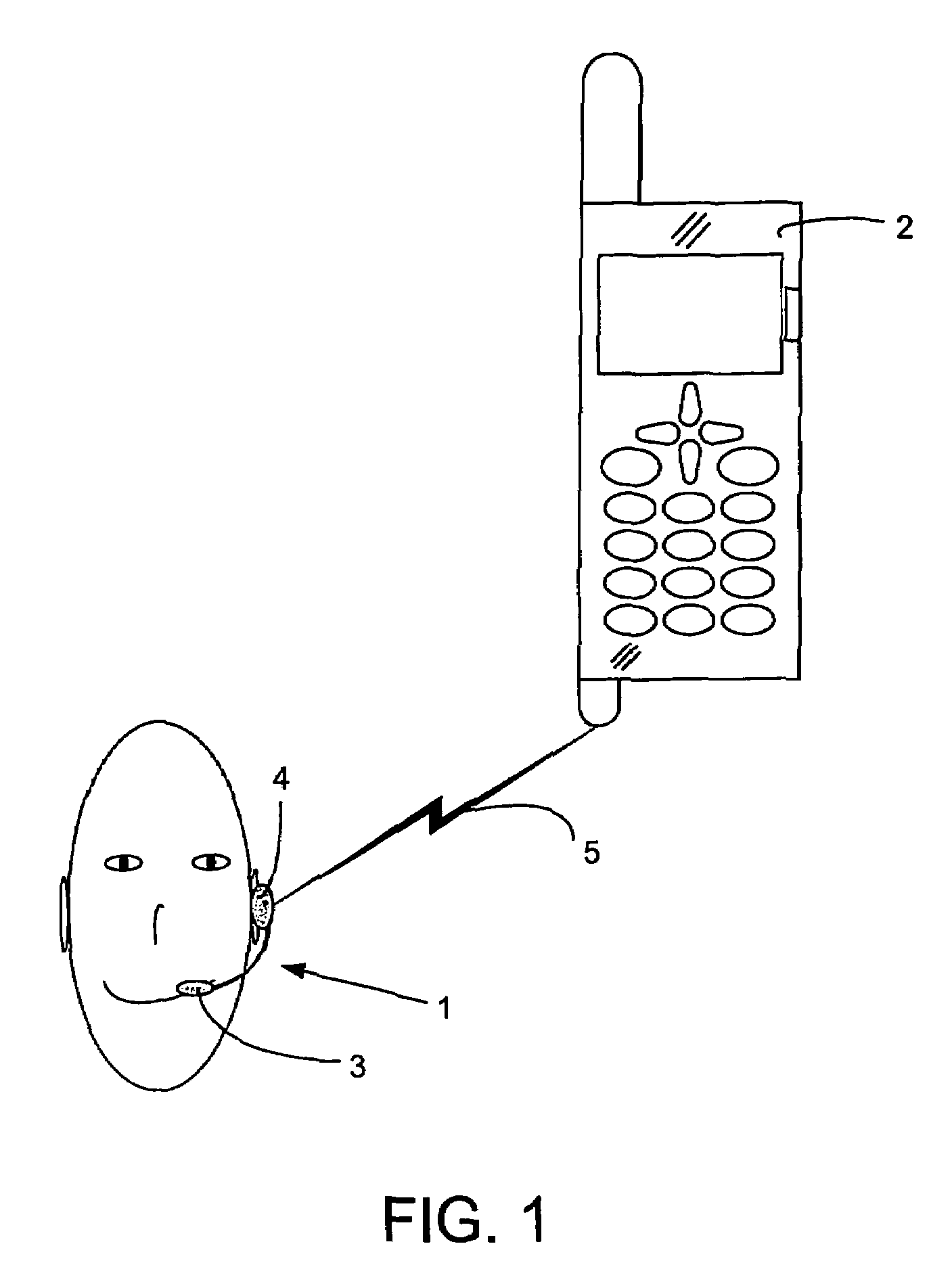
[0033]In FIG. 1 is a small portable communication device illustrated as a headset 1, which is adapted for wireless communication with a mobile telephone 2. The small portable device could be any electronic communication device, which has to be small to meet user preferences and which is adapted to communicate wirelessly with another communication device, which may be stationary or portable.

[0034]In the following, reference will be made to a headset 1 and a mobile telephone 2. However, this is only for convenience and the illustrated headset 1 and mobile telephone 2 are only for exemplifying purposes and should not be taken as limiting the scope of the invention.

[0035]The headset 1 comprises a microphone 3 and a loudspeaker 4, through which a user of the headset 1 may receive and transmit speech to the mobile telephone 2 through a wireless connection 5. Also, it is equally possible to communicate any data between the small portable device and the mobile telephone 2.

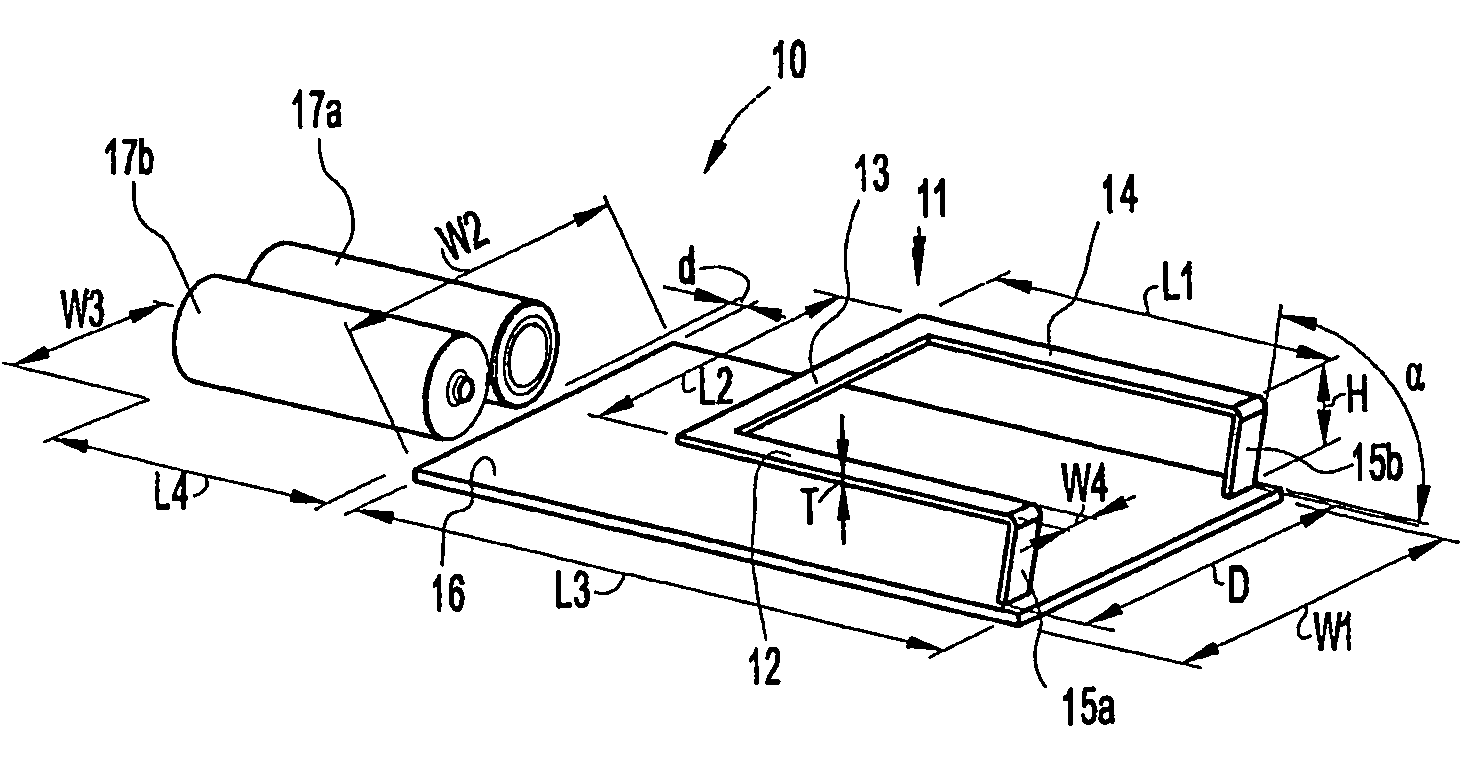
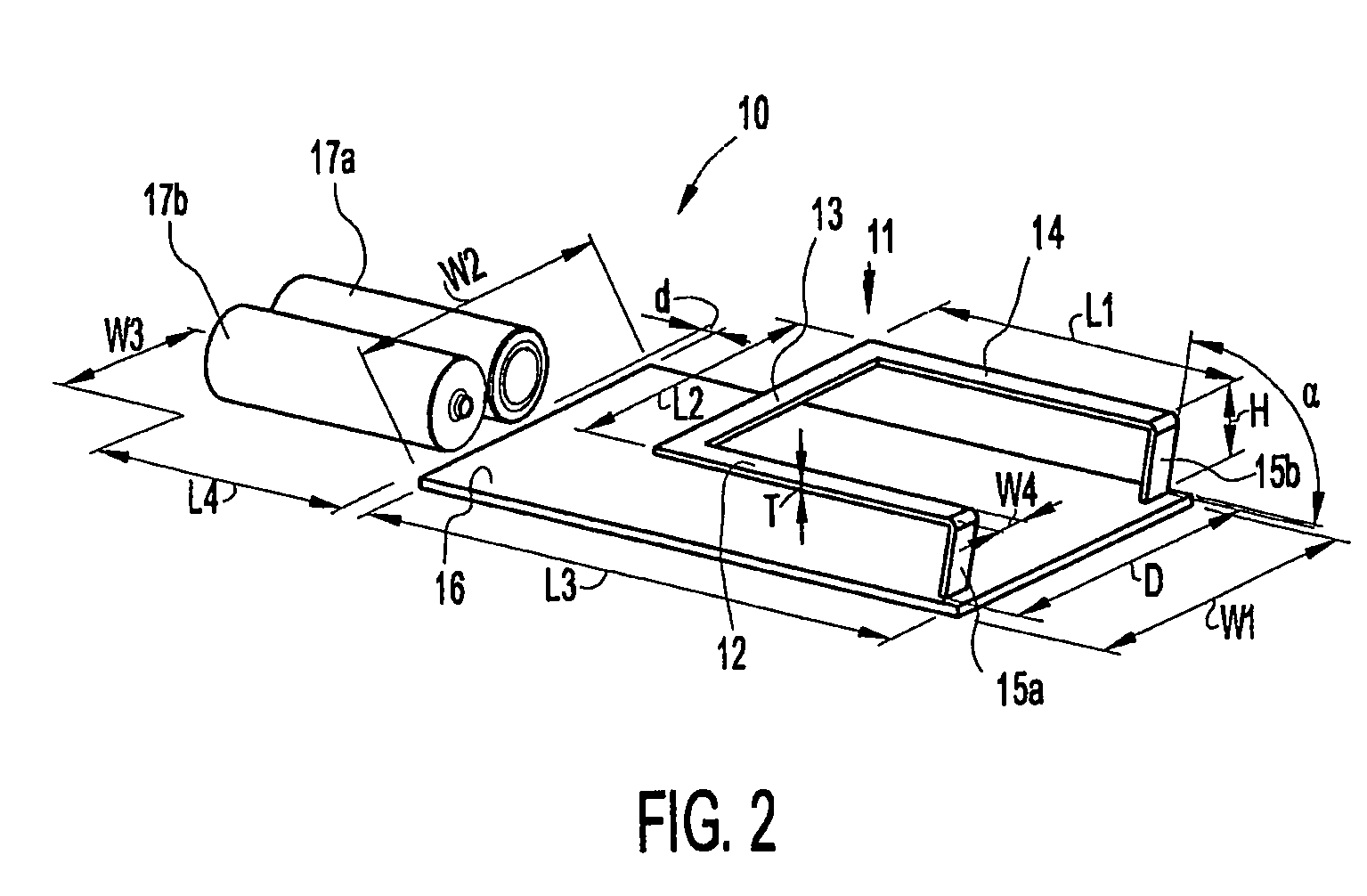
[0036]In FIG. 2 a ...


PUM


Abstract

An antenna device for a portable device has an antenna loop of conducting material to be connected to radio circuitry in the portable device. The antenna loop is positioned opposite a ground plane of a PCB. Also, the antenna device also comprises at least one battery, which is positioned in the extension of a first side of the PCB, and acts as an extension of the ground plane of the PCB.

Description

RELATED APPLICATIONS[0001]The present application is a 35 U.S.C. §371 national phase application of PCT International Application No. PCT / EP03 / 006109, having an international filing date of Jun. 11, 2003 and claiming priority to European Patent Application No. 02013085.2, filed Jun. 13, 2002, European Patent Application No. 02018940.3, filed Aug. 26, 2002 and U.S. Provisional Application No. 60 / 407,886 filed Sep. 3, 2002, the disclosures of which are incorporated herein by reference in their entireties. The above PCT International Application was published in the English language and has International Publication No. WO 03 / 107473.FIELD OF THE INVENTION[0002]The present invention relates to an antenna device for use in a small portable device. More specifically, the invention relates to a wideband antenna having sufficient efficiency for meeting the requirements of different communications protocols. Also, the antenna reduces the power consumption of the small portable device so it c...

Claims


Application Information

Patent Timeline
Patent Type & Authority Patents(United States)
IPC IPC(8): H01Q1/24H01Q1/48
CPCH01Q1/243H01Q1/48H01Q7/00
Inventor ROSENBERG, JOHAN ANTON EDUARDSCHREUDER, JOHANNES LUCASUILDRIKS, TJAPKO
Owner SONY CORP
Why Eureka
Try Eureka