
Subminiature bone vibrating speaker using the diaphragm and mobile phone thereby

a subminiature bone and diaphragm technology, applied in the direction of transducer details, electrical transducers, telephone set constructions, etc., can solve the problems of too many problems for too low output sound pressure, and too many problems for the commercial implementation of the utility model. achieve the effect of reducing power consumption and driving voltag

Inactive Publication Date: 2008-01-15
LEE OUG KI +2
View PDF10 Cites 10 Cited by
  • Summary
  • Abstract
  • Description
  • Claims
  • Application Information

AI Technical Summary

Benefits of technology

[0018]An object of the present invention is to provide a subminiature bone conduction speaker by using a vibrating plate and a mobile phone having the subminiature bone conduction speaker capable of reducing a driving voltage and thus reducing power consumption.
[0021]Still another object of the present invention is to provide a subminiature bone conduction speaker by using a vibrating plate and a mobile phone having the subminiature bone conduction speaker capable of resisting external impact by a yoke and a magnet being disposed at a lower portion
[0024]In the aforementioned subminiature bone conduction speaker, the acoustic vibrating plate may be made of beryllium copper, so that the acoustic vibrating plate can be produced to have thin thickness and the elastic force of the acoustic vibrating plate can be increased. In addition, the ring type magnet may be made of Nd material, so that large intensity of magnet field can be generated by small size of the ring type magnet.

Problems solved by technology

However, some of the human beings having auditory disorders such as have disorders of external ears or middle ears, presbycusis which is a hearing loss that gradually occurs as they grow older, and hearing loss as an occupational disease can not hear the sound in the only specific frequency range or over the all frequency range.
However, bone conduction telephone and the hearing aid vibrator by using the piezoelectric device according to the utility model are too theoretical to be implemented.
The utility model has so many problems for its commercial implementation.
Since the piezoelectric device has high impedance, the output sound pressure is too low and the miniaturization of the products is too difficult.
However, the conventional bone conduction speaker has a problem that high driving voltage and high power consumption are necessary to vibrate the yoke, the magnet, and the upper plate since the yoke, the magnet, and the upper plate serve as parts for generating the magnetic field as well as parts of vibrating upwardly and downwardly.
Therefore, the conventional bone conduction speaker has another problem that it is impossible to miniaturized and be employed to a subminiature mobile phone, a subminiature headset, a hearing aid apparatus, and so on.
Therefore, the conventional bone conduction speaker has still another problem that it is impossible to transmit the vibration of the mastoid to the user accurately since the mastoid which is contacted to the bone skull of the user is difficult to vibrate upwardly and downwardly due to heavy weights of the mastoid, the yoke, the magnet, and the upper plate.
In addition, the conventional bone conduction speaker has further still another problems that it may be easily being out of order due to any infinitesimal external impacts and its reliability may be being deteriorated since the internal parts such as the yoke and the magnet for generating the magnetic field are disposed at the upper portion of the bone conduction speaker.

Method used


Image

  • Subminiature bone vibrating speaker using the diaphragm and mobile phone thereby
  • Subminiature bone vibrating speaker using the diaphragm and mobile phone thereby
  • Subminiature bone vibrating speaker using the diaphragm and mobile phone thereby

Examples


Embodiment Construction

[0032]Now, the preferred embodiments according to the present invention will be described in details with reference to the accompanying drawings.

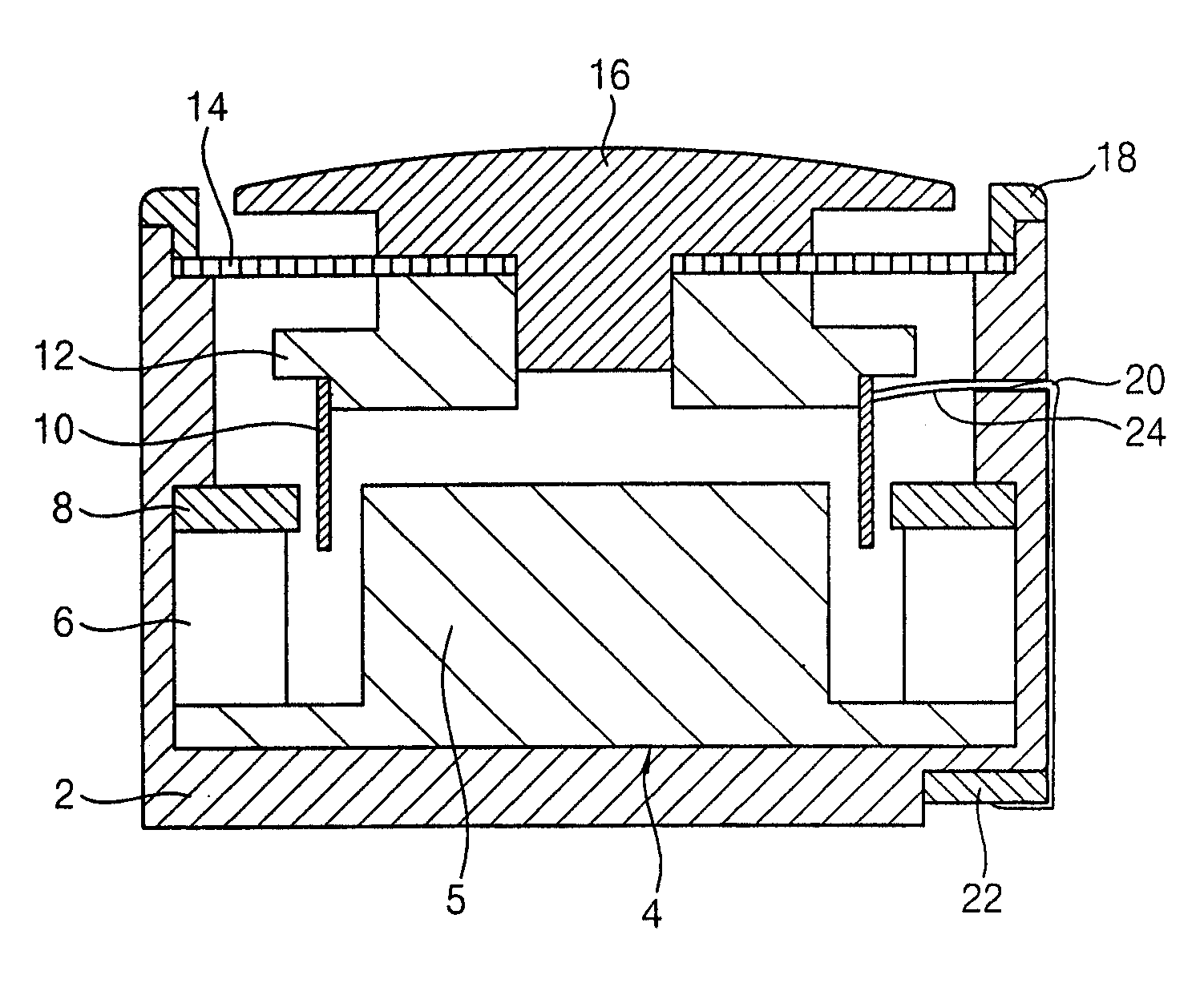
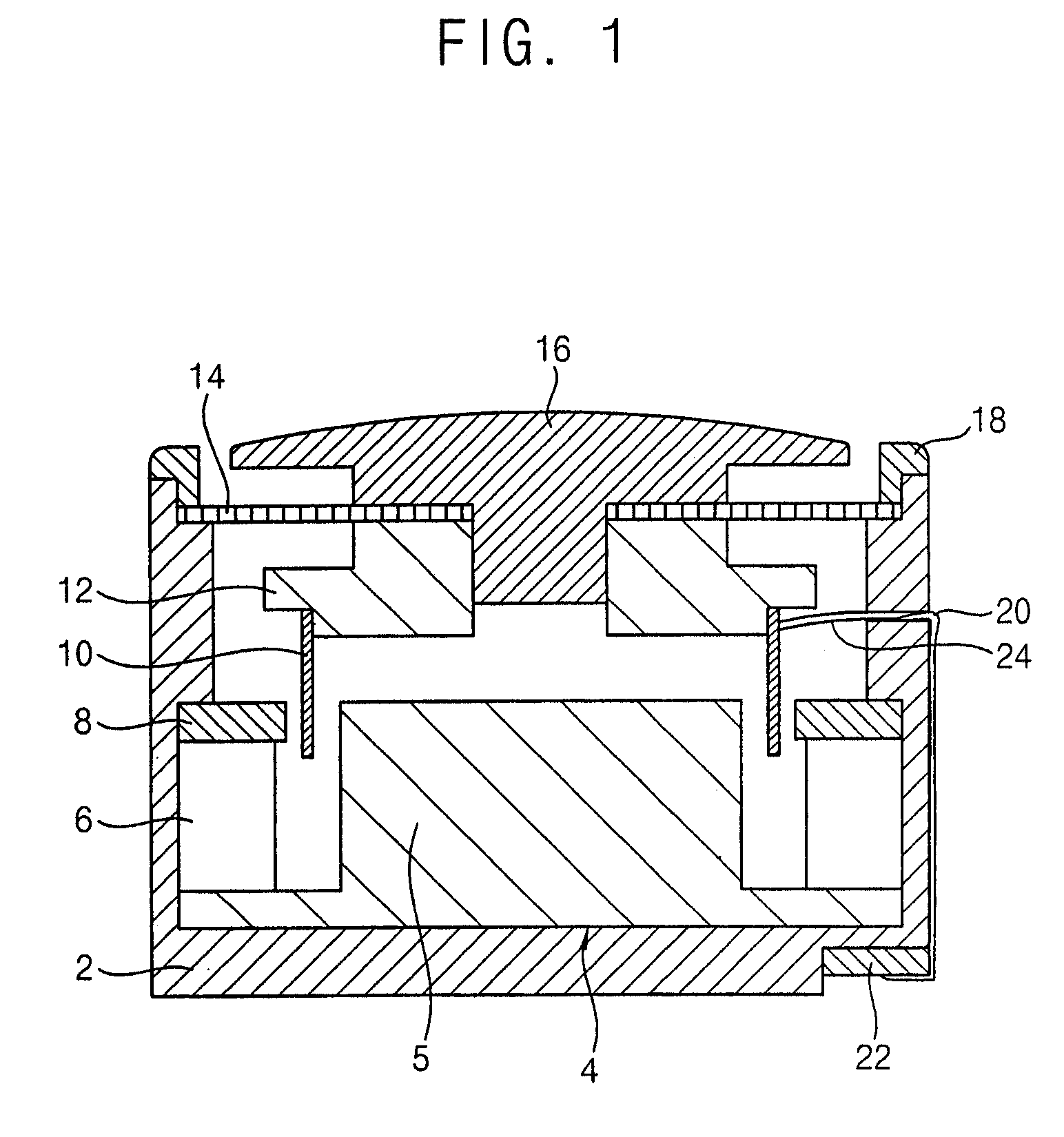
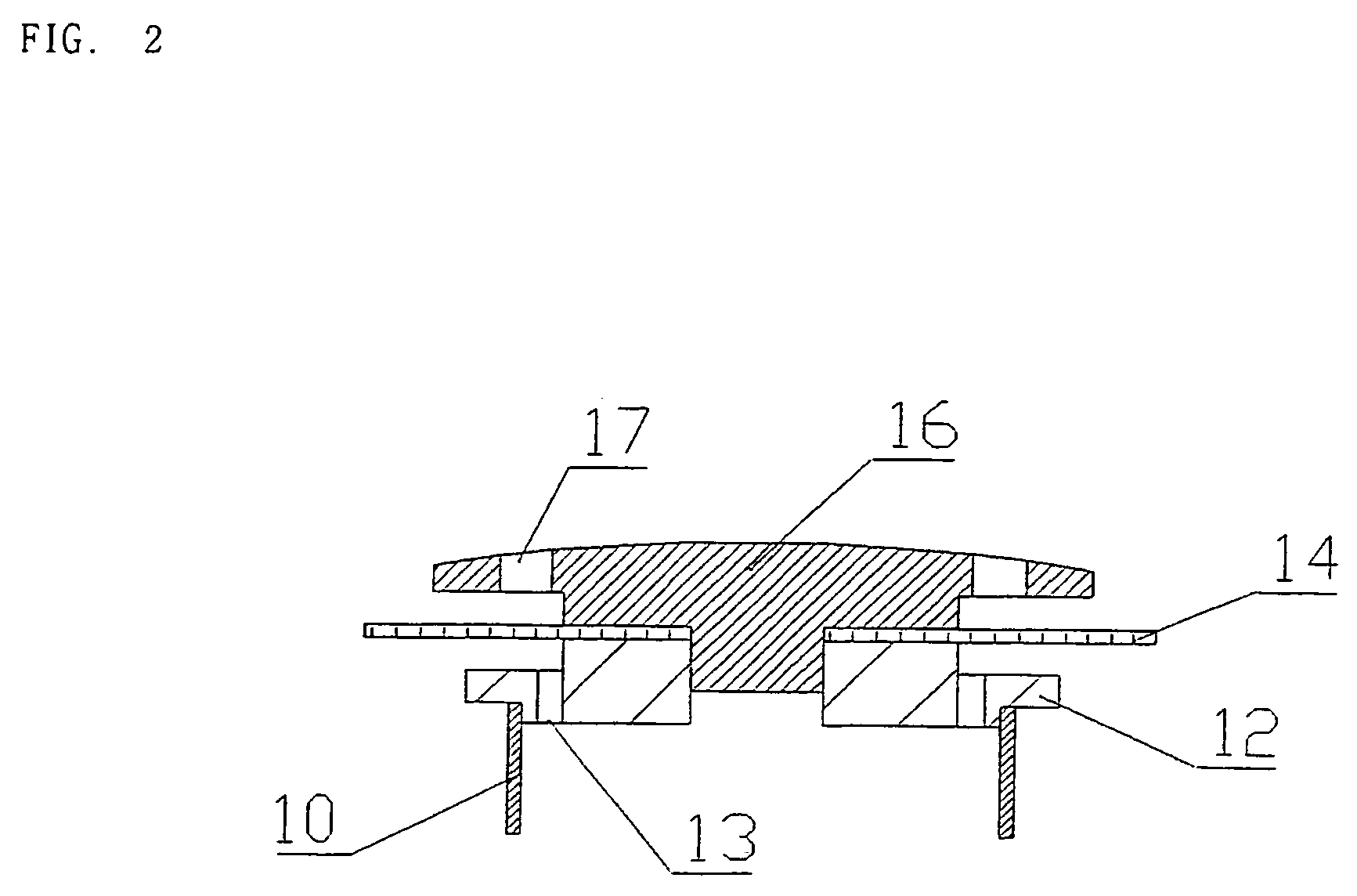
[0033]FIG. 1 is a cross sectional view of a subminiature bone conduction speaker according to an embodiment of the present invention, and FIG. 2 is an enlarged cross sectional view illustrating a mastoid, an acoustic vibrating plate, an auxiliary vibrating plate, and a voice coil.

[0034]The subminiature bone conduction speaker according to the present invention comprises a body 2 which is constructed with a plastic material for sub-miniaturization. The body 2 has a shape of a cylinder with its upper portion opened. A through hole 20 is formed to connect with external portion at the one side wall of the body 2. A connection terminal 22 is formed at the outer bottom portion of the body 2.

[0035]The edge of the outer bottom portion of the body has a recess. In the interior of the body, a yoke 4 and a protrusion 5 of the yoke 4 are formed at the ...


PUM


Abstract

The present invention relates to a subminiature bone conduction speaker by using a vibrating plate and a mobile phone having the subminiature bone conduction speaker. A subminiature bone conduction speaker using a vibrating plate according to the present invention comprises a body having a shape of a cylinder of which upper portion is opened; yoke which is disposed in a lower portion of the body and of which center has a protrusion; a ring type magnet which is formed on the edge of the yoke and apart from an end portion of the protrusion by a predetermined clearance; an upper plate which is formed on the magnet; a mastoid which is contacted to bone conduction of a user and by which vibration is transmitted to the user; an acoustic vibrating plate which is inserted at a lower side of the mastoid to cover the opening portion of the body and which is made of an elastic material; an auxiliary vibrating plate which is inserted under the acoustic vibrating plate which is inserted to the mastoid; a voice coil which is attached to the auxiliary vibrating plate and which is inserted between the end portion of the protrusion of the yoke and the ring type magnet; a front cap for fixing the acoustic vibrating plate on the body; and a electrical signal input unit for inputting an electric signal to the voice coil.

Description

CROSS-REFERENCE TO RELATED APPLICATIONS[0001]This application is a National Stage application under 35 U.S.C. §371 of and claims the benefit of International Application No. PCT / KR03 / 00542, filed on Mar. 19, 2003, published in the English language on Feb. 26, 2004 as International Publication Number WO 2004 / 017532 A1, which claims priority to Korean Application No. 10-2002-48318 filed on Aug. 16, 2002, all of which are hereby incorporated by reference.TECHNICAL FIELD[0002]The present invention relates to a subminiature bone conduction speaker by using a vibrating plate and a mobile phone having the subminiature bone conduction speaker, and more specifically, to a subminiature bone conduction speaker by using a vibrating plate capable of directly vibrating skull bone and stimulating auditory nerve so that sound can be heard and a mobile phone having the subminiature bone conduction speaker.BACKGROUND ART[0003]Generally, sound that is heard by human beings is a wave. The sound wave th...

Claims


Application Information

Patent Timeline
Patent Type & Authority Patents(United States)
IPC IPC(8): H04R25/00H04R9/02H04B1/38H04M1/02H04M1/03H04R1/00H04R1/02H04R7/02H04R9/06
CPCH04B1/385H04M1/03H04R9/066H04R25/00H04R2460/13H04R2499/11H04R25/606H04B1/40
Inventor LEE, OUG-KIKIM, JOO-BAE
Owner LEE OUG KI
Learn More