
Branch predicting apparatus and branch predicting method

a branch prediction and branch prediction technology, applied in the direction of instruments, computation using denominational number representation, program control, etc., can solve the problems of inability to fix the return destination of the return instruction, the branch prediction also has a significant penalty, and the branch prediction is less effective for the branch

Active Publication Date: 2008-01-15
FUJITSU LTD
View PDF15 Cites 12 Cited by
  • Summary
  • Abstract
  • Description
  • Claims
  • Application Information

AI Technical Summary

Benefits of technology

This approach enables highly accurate branch prediction by correctly identifying branch destinations, even when multiple call instructions are pending, by effectively managing and prioritizing return address stack entries.

Problems solved by technology

However, a processor for performing branch prediction predicts a branch and executes an instruction after the predicted branch speculatively.
However, when the prediction does not come true, since it is necessary to flush a pipeline and re-execute processing from a part where a branch instruction is given, the branch prediction also has a significant penalty.
However, the branch prediction is less effective for a branch according to a return instruction from a subroutine.
However, in general, since the subroutine is called from various sections of a program, a return destination of the return instruction is not fixed.
Therefore, even if the branch destination is predicted according to a history in the past, the prediction is not always correct.
Therefore, when the return instruction is detected by the branch history because of read-ahead or the like of an instruction stream before the execution of the call instruction is completed, there is a problem in that the address of the return destination is not stored in the return address stack and accuracy of branch prediction falls.
However, the technique proposed in the above literature has a problem in that it is not taken into account that, after a call instruction is detected by the branch history, another call instruction is detected by the branch history until the execution of the call instruction is completed.

Method used


Image

  • Branch predicting apparatus and branch predicting method
  • Branch predicting apparatus and branch predicting method
  • Branch predicting apparatus and branch predicting method

Examples


first embodiment

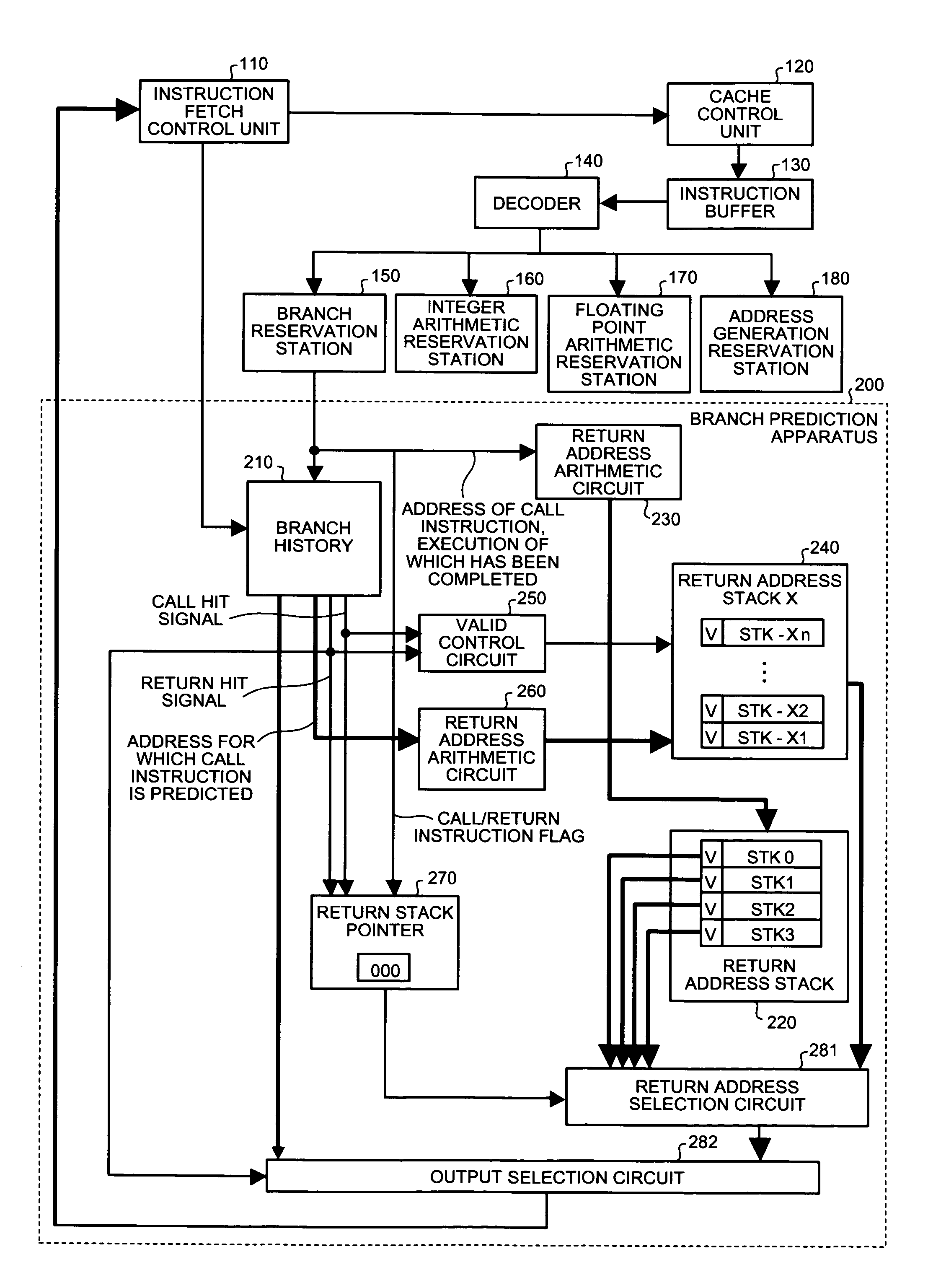
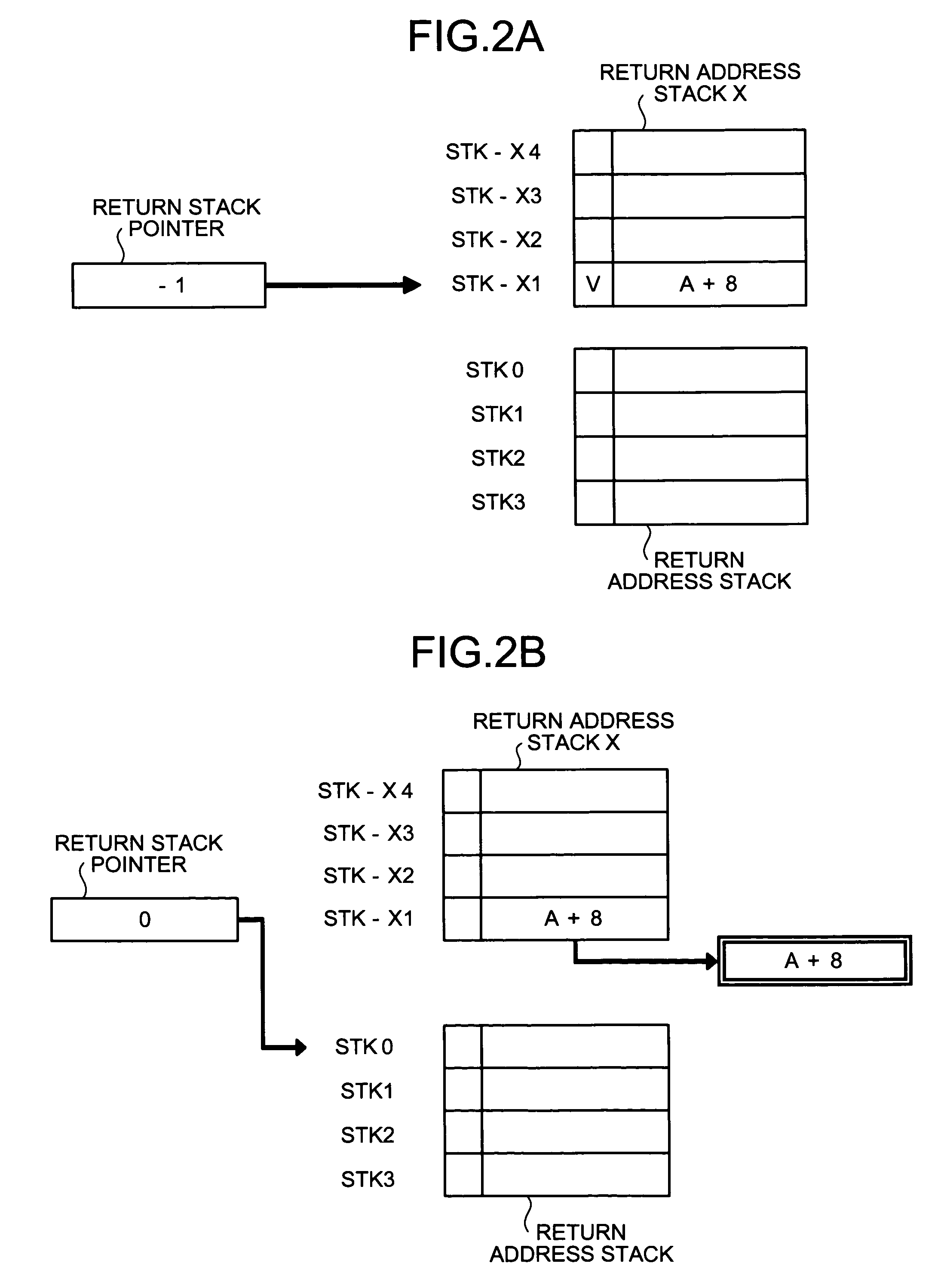
[0087]As described above, when a valid entry is present in the return address stack X, an address of a branch destination is acquired from a valid entry, a value of which is stored in the return address stack X last, regardless of a value of the return stack pointer. Thus, it is possible to perform highly accurate branch prediction even when there are plural call instructions that have been detected by the branch history but execution of which has not been completed.

[0088]If the branch prediction system explained according to the first embodiment is used, it is possible to perform highly accurate branch prediction even when there are plural call instructions that have been detected by the branch history but execution of which has not been completed. However, there is a problem in that, to improve accuracy of branch prediction using this branch prediction system, entries in the number sufficient for the return address stack X have to be prepared, leading to an increase in cost.

second embodiment

[0089]Thus, according to the present invention, a branch prediction system, which can perform branch prediction highly accurately when there are plural call instructions that have been detected by the branch history but execution of which has not been completed while holding down the number of entries in the return address stack X, will be explained.

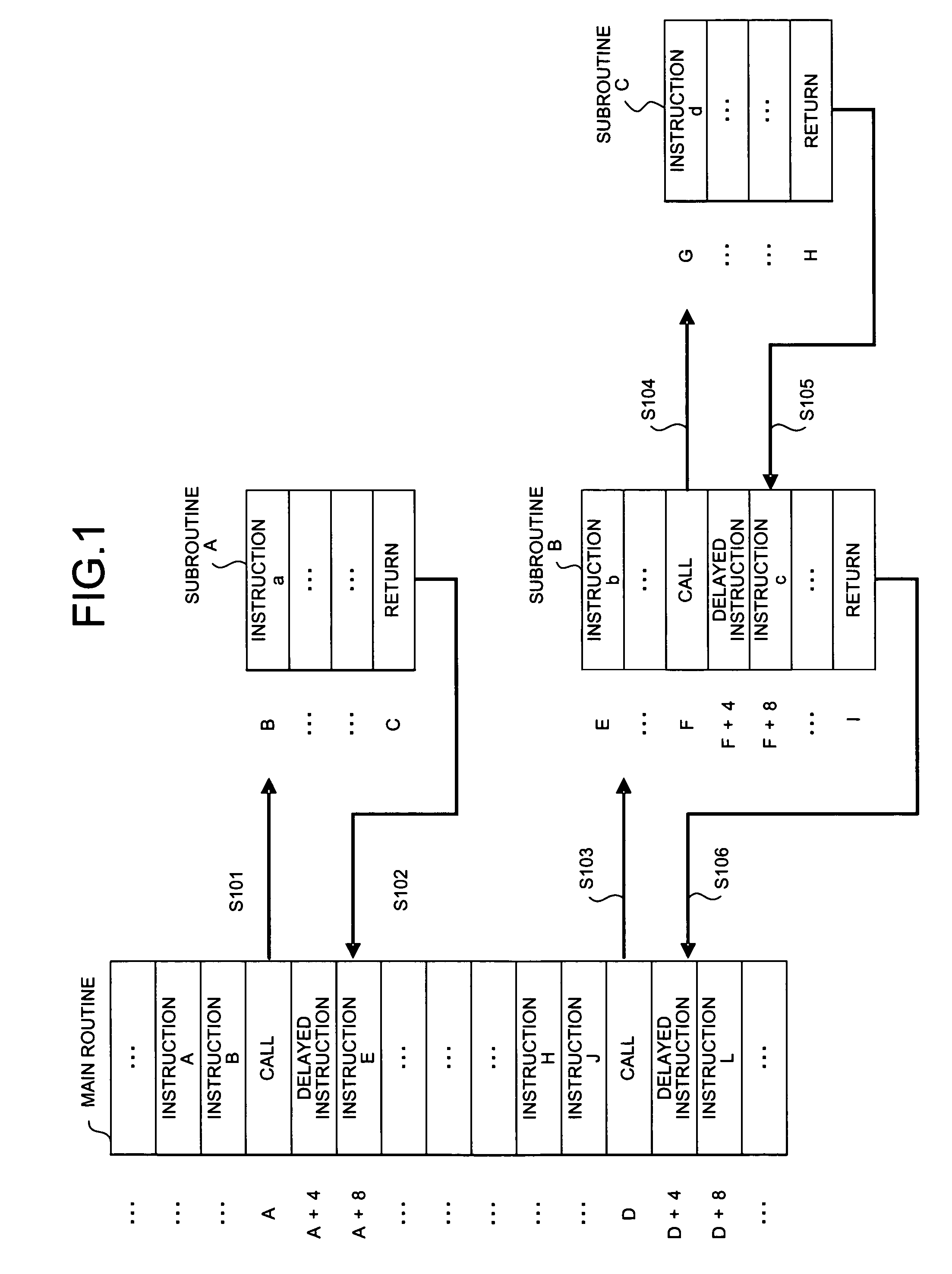
[0090]FIG. 6 is a sample diagram of an instruction stream for explaining an operation of a branch predicting apparatus according to the second embodiment. As shown in the figure, a main routine calls a subroutine A according to a call instruction in an address A (step S201). After executing several instructions, the subroutine A returns to the main routine according to a return instruction in an address C (step S202). An address of a destination to which the subroutine A returns according to the return instruction is an 8-byte-address after the address of the call instruction, that is, A+8.

[0091]The main routine calls a subroutine B acco...

third embodiment

[0172]FIG. 20 is an explanatory diagram for explaining an outline of the branch prediction system according to the As shown in the figure, in the branch prediction system according to the present embodiment, an X valid table and a call hit counter are used.

[0173]The X valid table is a table for managing validity of respective entries in an imaginary return address stack X. Each bit of the return hit table corresponds to one entry in the imaginary return address stack X and takes 0 as an initial value. If a bit has a value 0, this indicates that an imaginary entry corresponding thereto is invalid, and if a bit has a value 1, this indicates that an imaginary entry corresponding thereto is valid.

[0174]In the X valid table, a value 1 is set in order from a least significant bit XV1 every time a call instruction is detected and a bit with a most significant value 1 is reset to a value 0 every time a return instruction is detected. In addition, a value of the least significant bit is dis...


PUM


Abstract

A branch history stores execution history information of branch instructions, and predicts presence of a branch instruction and a corresponding branch destination. A first return address stack stores, when an execution of a call instruction of a subroutine is completed, address information of a return destination of a corresponding return instruction. A second return address stack stores, when presence of a call instruction of a subroutine is predicted, address information of a return destination of a corresponding return instruction. An output selecting unit selects, when presence of a return instruction is predicted, if address information is stored in the second return address stack, the address information as a result of the branch prediction with a highest priority, and outputs the address information selected.

Description

BACKGROUND OF THE INVENTION[0001]1) Field of the Invention[0002]The present invention relates to a branch predicting apparatus and a branch predicting method that perform branch prediction in a processor of a pipeline system. In particular, the present invention relates to a branch predicting apparatus and a branch predicting method that can keep accuracy of a branch prediction high when plural call instructions are detected by a branch history prior to completion of execution of a call instruction.[0003]2) Description of the Related Art[0004]Conventionally, a method of branch prediction is widely used for speed-up of processing in a processor of a pipeline system. When a branch is present in a program, it is essentially necessary to stop a pipeline until the branch is defined. However, a processor for performing branch prediction predicts a branch and executes an instruction after the predicted branch speculatively.[0005]The branch prediction has a significant advantage that, when ...

Claims


Application Information

Patent Timeline
Patent Type & Authority Patents(United States)
IPC IPC(8): G06F9/38
CPCG06F9/3806G06F9/3844G06F9/30054G06F9/323
Inventor YOKOI, MEGUMI
Owner FUJITSU LTD
Learn More