Combination of injector-ejector for fuel cell systems

a fuel cell and injector technology, applied in the direction of fuel cells, cell components, reactant parameter control, etc., can solve the problems of affecting the overall energy efficiency of the fuel cell system, reducing fuel utilization, and disrupting the chemical reaction

Active Publication Date: 2008-01-22
GM GLOBAL TECH OPERATIONS LLC
View PDF4 Cites 81 Cited by
  • Summary
  • Abstract
  • Description
  • Claims
  • Application Information

AI Technical Summary

Benefits of technology

[0015]According to one embodiment of the present invention, the injector / ejector system includes a hydrogen supply pressure controller for controlling the pressure of the hydrogen supply from a pressurized tank to the injector within the injector / ejector system. The density and constituency of the anode exhaust gas from the fuel cell system is sensed by a suitable sensor, and the pressure of the hydrogen applied to the injector is increased or decreased accordingly by the pressure controller so that the hydrogen supply flow effectively draws the exhaust gas through the anode exhaust outlet. In this embodiment, a pin-hole orifice is provided adjacent to the pressurized tank so that if the high-pressure conduit between the tank and the pressure controller is ruptured, a minimal amount of hydrogen will escape from the tank before the leak can be detected and the regulator turned off.

Problems solved by technology

If free electrons or other substances could travel through the electrolyte, they would disrupt the chemical reaction.
Reduced fuel utilization is therefore a major disadvantage of this ejector re-circulation method where nitrogen is present in the anode gas.
However, pumping power increases with re-circulation load, thus detracting from the overall energy efficiency of the fuel cell system.

Method used


Image

  • Combination of injector-ejector for fuel cell systems
  • Combination of injector-ejector for fuel cell systems
  • Combination of injector-ejector for fuel cell systems

Examples


Embodiment Construction

[0036]The following description of the embodiments of the invention directed to an injector / ejector system for a fuel cell is merely exemplary in nature and is in no way intended to limit the invention, or its application and uses.

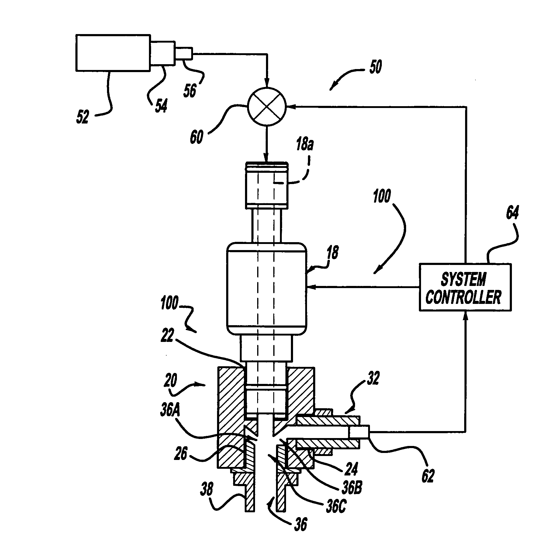
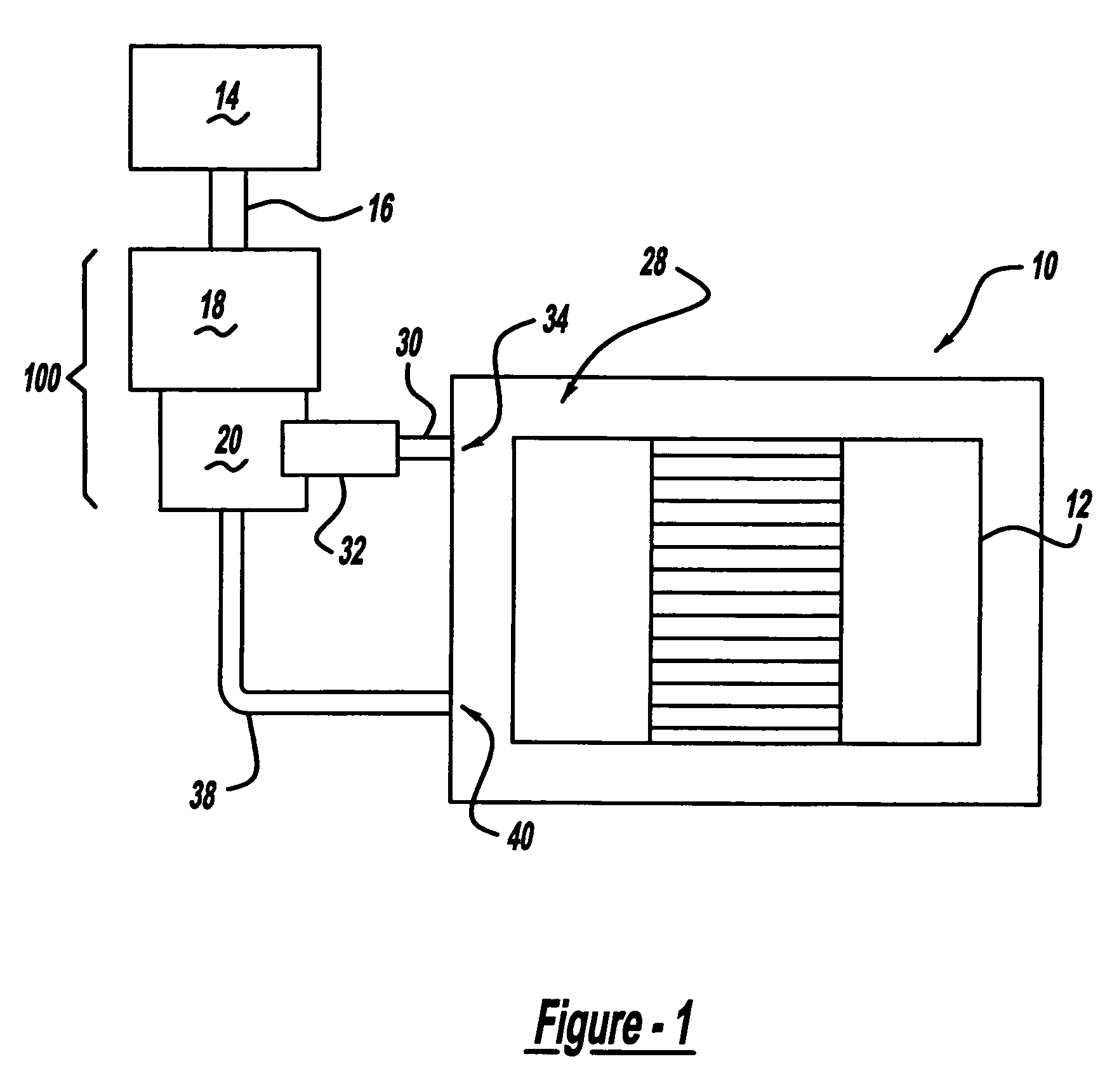
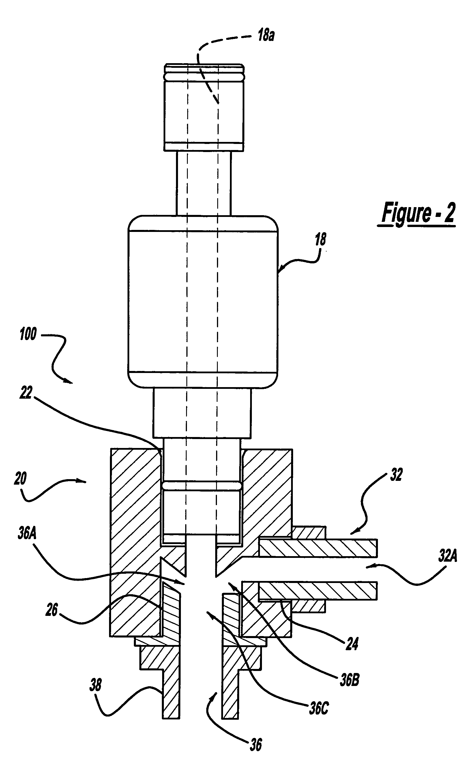
[0037]Referring to FIGS. 1 and 2, there is shown a schematic illustration of a fuel cell system 10, in accordance with the general teachings of the present invention, as well as a sectional illustration of a combined injector / ejector system 100 for use in conjunction with the fuel cell system 10, in accordance with one embodiment of the present invention.

[0038]The fuel cell system 10 includes at least one fuel cell 12, and generally a plurality of fuel cells, referred to as a stack. A first gas source 14, such as a pressurized H2 tank on a vehicle, is provided for storing a pressurized gas, such as, but not limited to, hydrogen (H2). An optional conduit 16 is provided in fluid communication with the first gas source 14.

[0039]An injector system 18 is provid...


PUM

PropertyMeasurementUnit
pressureaaaaaaaaaa
pressureaaaaaaaaaa
pressureaaaaaaaaaa

Abstract

A fuel cell system including a combined injector / ejector system. The pressure of a hydrogen gas being injected into the fuel cell system by the injector acts as a pump that draws an anode exhaust gas being carried by the ejector back into the fuel cell system. The respective gases mix together in proximity to the ejector prior to being introduced back into the fuel cell system. A pressure controller can be provided to control the pressure of the hydrogen gas applied to the injector to more effectively draw the anode exhaust gas. In this manner, the need for a separate pump for the ejector, and the energy required for its operation, is eliminated or at least lessened, thus increasing the overall energy efficiency of the fuel cell system.

Description

CROSS-REFERENCE TO RELATED APPLICATIONS[0001]This application claims the benefit of the filing date of U.S. Provisional Application 60 / 487,997, titled “Combination of Injector / Ejector for Fuel Cell Systems,” filed Jul. 17, 2003.BACKGROUND OF THE INVENTION[0002]1. Field of the Invention[0003]The present invention relates generally to fuel cell systems and, more particularly, to a new and improved fuel cell system having a combined injector / ejector system.[0004]2. Discussion of the Related Art[0005]A fuel cell is a device that generates electricity by a chemical reaction. Every fuel cell has two electrodes, one positive and one negative, called, respectively, the cathode and the anode. The reactions that produce electricity take place at the electrodes. Every fuel cell also has an electrolyte, which carries electrically charged particles from one electrode to the other, and a catalyst, which speeds the reactions at the electrodes. Hydrogen is the basic fuel, but fuel cells also requir...

Claims


Application Information

Patent Timeline
Patent Type & Authority Patents(United States)
IPC IPC(8): H01M2/00H01M8/04
CPCH01M8/04089H01M8/04201Y02E60/50
Inventor PECHTOLD, RAINERSIEPIERSKI, JAMES S.
Owner GM GLOBAL TECH OPERATIONS LLC
Why Eureka
Try Eureka