
Pointing stick with function pad for two handed operation

a function pad and pointing stick technology, applied in the field of computer input devices, can solve problems such as large changes, bogus clicks, and large changes, and achieve the effects of generating bogus clicks, and reducing the number of clicks

Inactive Publication Date: 2008-01-22
FAETH MICHAEL G
View PDF16 Cites 6 Cited by
  • Summary
  • Abstract
  • Description
  • Claims
  • Application Information

AI Technical Summary

Benefits of technology

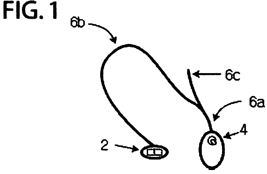
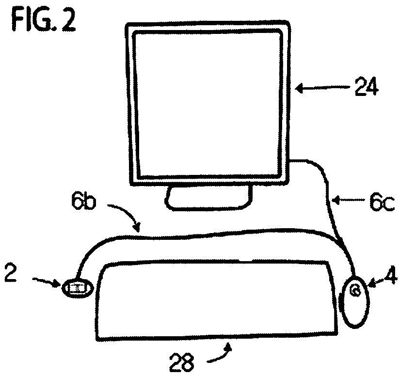
"The present invention is a computer pointing device that allows users to easily input commands on a computer by using their hands and fingers. The device has two modules: a first module with a pointing device and a second module with touch-sensitive devices. The first module can be positioned at a comfortable angle for the user's hand, while the second module has a flat surface for easy access. The first module can be used with a mouse or a joystick, while the second module can be used with fingers or a stylus. The device also has a comfortable grip and a wrist support for long periods of use. The technical effects of the invention include improved efficiency and comfort for users who spend a lot of time on the computer."

Problems solved by technology

However, since there is no circuitry controlling the access to the computer of the various commands, certain results may occur which are undesirable.
Individuals with access issues may find themselves hitting the standard mouse's button by accident, thus generating bogus clicks or turning a single click into a double click, etc.
The natural rest position for any two people will be different, but for those of differing enablements or differing work needs, the changes may be quite large.
Traditional joysticks normally use a full five fingered grip which may present access issues to some users.
Different individuals will have different accessibility issues.
Thus, while the scheme above might work for a user having a “click and drag” issue, it might not be appropriate for one whose main interest is precision placement of the cursor during clicking.
However, this short-cut comes with a disadvantage.
In particular, the unitary device of the invention is no longer truly portable in such an embodiment.

Method used


Image

  • Pointing stick with function pad for two handed operation
  • Pointing stick with function pad for two handed operation
  • Pointing stick with function pad for two handed operation

Examples


Embodiment Construction

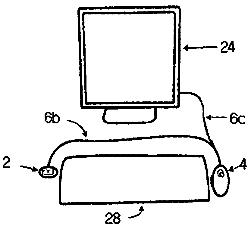
[0140]The term “computer pointing device” as used herein refers to such items as joysticks, mice, track balls, touch pads, pressure sensitive pointing devices of any now known or later-developed manner, style, type, specification. The term joystick, however, generally refers to devices having a base portion and a small handle protruding generally vertically therefrom, in which motion of the handle is translated as cursor motion.

[0141]Understanding the invention may be understood best by comparison of the invention and the prior art in terms of command flow paths.

[0142]FIG. 12 is a PRIOR ART view of the control path of one type of prior art. First cable 100 and second cable 102 are single cables attached to two different joystick devices 104, 106. Prior art in which two joysticks are used, or two of other types of input devices, may be found easily. Each joystick has an analog input device for cursor motions and a clicking device such as a button, and each occupies a separate one of ...


PUM


Abstract

A computer input device has two modules, each module located at the natural resting position of one of the computer user's corresponding hands on a work surface. The first module has a pointing device, while the second module has a plurality of touch sensitive devices such as buttons or skin capacitance detectors. The second module is substantially flat and sends to the computer commands which translate to those of left and right clicks and / or scrolls. The first module has a pointing stick allowing easy hand access and further allowing the stick to be held in a pencil grip or with the thumb and opposing finger or fingers for pointing. The command translation and other variables may be programmed to suit the user's accessibility needs.

Description

CROSS-REFERENCE TO RELATED APPLICATIONS[0001]This invention claims the priority and benefit of U.S. Provisional Patent Application No. 60 / 440,216 filed Jan. 14, 2003 in the name of the same inventor, Michael Faeth, and entitled “TWO HAND COMPUTER INPUT DEVICE” and as disclosed in Disclosure Document No. 515675 dated Jul. 18, 2002 entitled “TWO-HAND COMPUTER INPUT DEVICE” in the name of the same inventor, Michael Faeth, and is a continuation-in-part application of U.S. patent application Ser. No. 10 / 754,864, presently accorded filing date Jan. 8, 2004 now abandoned, by the same inventor and also entitled “TWO HANDED COMPUTER INPUT DEVICE”, the specifications of which are hereby incorporated by reference.FIELD OF THE INVENTION[0002]This invention relates generally to computer input devices and specifically to “point and click” devices such as the computer mouse.STATEMENT REGARDING FEDERALLY FUNDED RESEARCH[0003]This invention was not made under contract with an agency of the US Govern...

Claims


Application Information

Patent Timeline
Patent Type & Authority Patents(United States)
IPC IPC(8): G09G5/00G06F3/033
CPCG06F3/0338G06F3/03543
Inventor FAETH, MICHAEL G.
Owner FAETH MICHAEL G
Learn More