Multivibrator protected against current or voltage spikes

a multi-vibrator and current or voltage technology, applied in the direction of electric pulse generator circuits, instruments, static storage, etc., can solve the problems of increasing the sensitiveness of the circuit to the external environment, upset is not predictable or very unlikely to be predicted, and may have relatively serious consequences on the downstream circuit, so as to improve the protection of the multi-vibrator

Active Publication Date: 2008-01-22
STMICROELECTRONICS SRL
View PDF10 Cites 12 Cited by
  • Summary
  • Abstract
  • Description
  • Claims
  • Application Information

AI Technical Summary

Benefits of technology

[0009]With regard to the foregoing, an object of the invention is to further improve the protection of multivibrators against current or voltage spikes.
[0011]An erroneous item of information is thus prevented from being written simultaneously to the set of storage nodes in the case where an upset occurs immediately at the input of a latch cell.
[0013]This multivibrator can furthermore comprise an input circuit suitable for formulating redundant data for the first latch cell. This further improves the protection of the multivibrator against upsets. For example, this input circuit comprises an inverter circuit for the inversion of an input data item, whose output is intended to be written to data storage nodes.

Problems solved by technology

On the down side, such circuits are increasingly sensitive to their external environment, and in particular to logic upsets due to an influx of energy coming from outside the circuit.
By definition, an upset is not predictable or is very unlikely to be predicted.
This type of upset appears in integrated circuits used for space applications, because of the radiation encountered beyond the atmospheric and magnetospheric layers that protect the earth.
An upset may have relatively serious consequences on the downstream circuit that it disturbs.
In contrast, if the change in voltage ΔV is higher, and especially if it is high enough to modify the value of a logic signal, then the consequences may be substantial.
In particular, a change in voltage ΔV generated by an upset may disturb the normal operation of a flip-flop multivibrator.
Now, an upset of substantial amplitude may cause the logic levels present on the input of each latch cell to switch when they are not imposed by a corresponding transfer port.
Such switching, that is to say the modification of the content of the latch cells, will, of course, have the consequence of introducing an error into the outputs from the multivibrator.

Method used


Image

  • Multivibrator protected against current or voltage spikes
  • Multivibrator protected against current or voltage spikes
  • Multivibrator protected against current or voltage spikes

Examples


Embodiment Construction

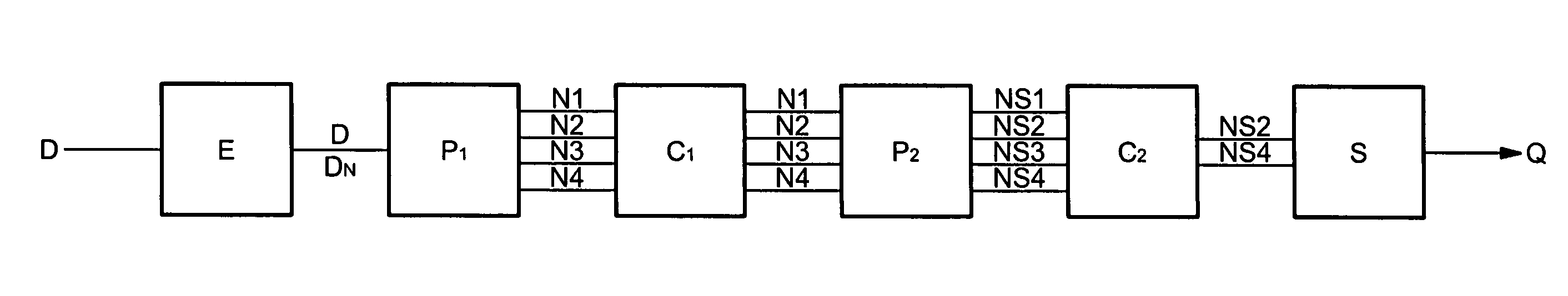
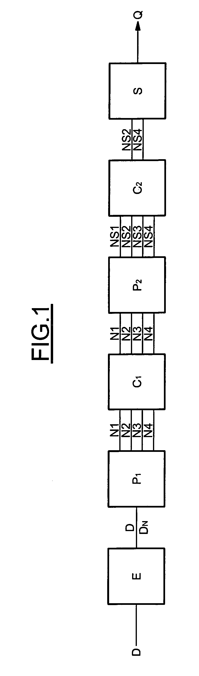
[0041]FIG. 1 shows the overall architecture of an example of an electronic diagram of a multivibrator of the flip-flop type protected against current or voltage spikes. As may be seen in this figure, such a multivibrator comprises: a first data transfer port P1 receiving, as input, data D and DN coming from an input circuit E; a first, master, data latch cell C1, used for temporarily storing the data coming from the transfer point P1; a second data latch cell C2, constituting a slave latch cell, into which the data coming from the first, master cell C1 is transferred; a second data transfer port P2; and an output circuit S.

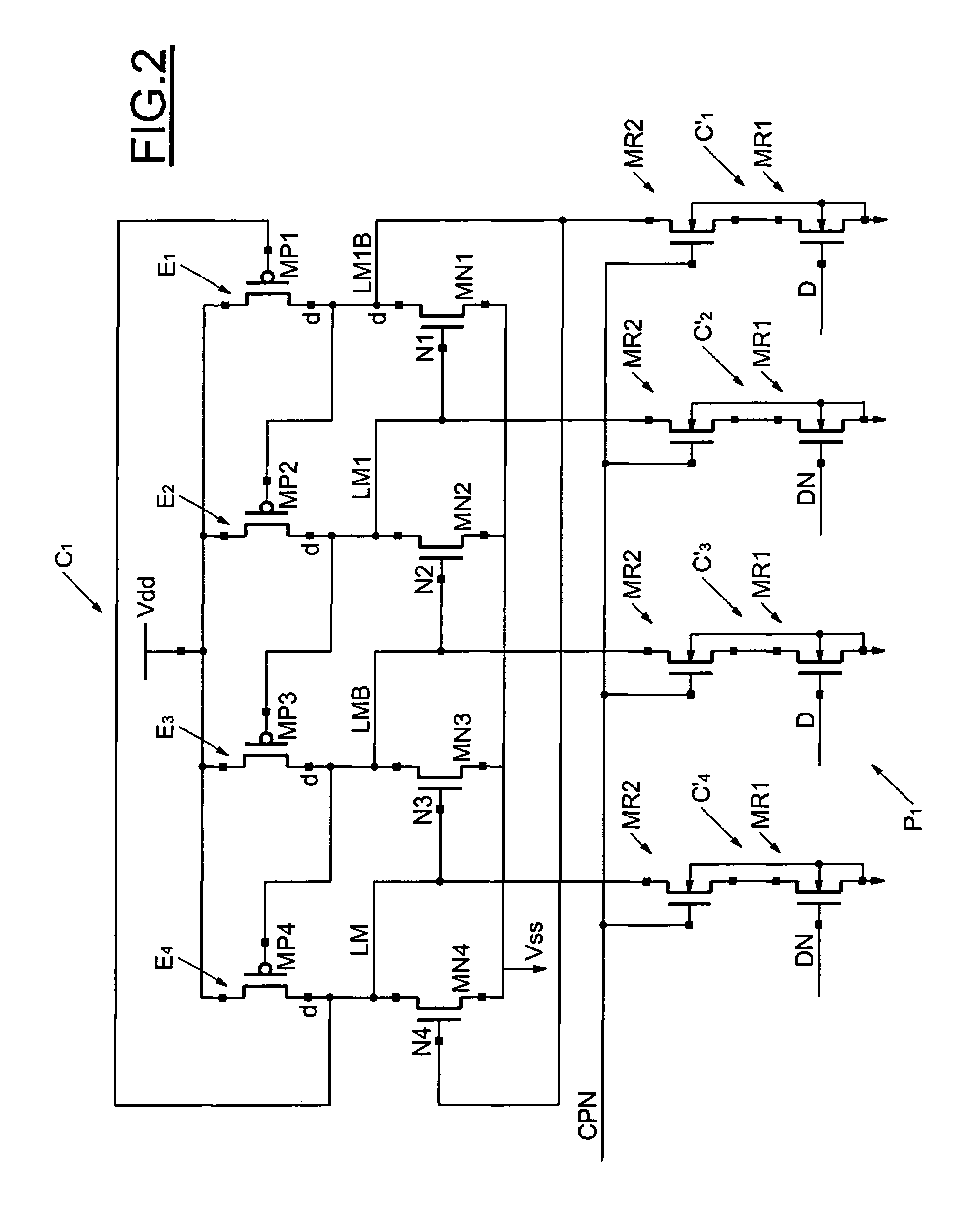
[0042]As may be seen in FIGS. 2 and 3, the master data latch cell comprises four sets of transistors E1, E2, E3 and E4 used for controlling the voltage level of four respective data storage nodes N1, N2, N3 and N4. Likewise, the slave data latch cell comprises four sets of transistors E1, E2, E3 and E4 used for controlling the voltage level of four respective data...


PUM


Abstract

The multivibrator is protected against current or voltage spikes and includes a first data transfer port that receives, as input, multivibrator input data, and a first / master latch cell connected on the output side of the first transfer port. A second / slave latch cell is included, and a second data transfer port is placed between the first and second latch cells. Each latch cell includes a set of redundant data storage nodes. The transfer ports each circuits / devices for writing data separately into each storage node.

Description

FIELD OF THE INVENTION[0001]The present invention relates to multivibrators protected against current or voltage spikes, particularly multivibrators of the flip-flop type. However, the invention applies in general to any type of multivibrator protected against such current or voltage spikes.BACKGROUND OF THE INVENTION[0002]The progressive and continuous miniaturization of electronic circuits makes it possible to obtain circuits that continue to increase in performance while continuing to decrease in size. On the down side, such circuits are increasingly sensitive to their external environment, and in particular to logic upsets due to an influx of energy coming from outside the circuit. A logic upset is a point state change or a transient state, resulting from a voltage spike and / or a current spike at a point in an integrated circuit. By definition, an upset is not predictable or is very unlikely to be predicted.[0003]Logic upsets may have different origins. A logic upset is, for exa...

Claims


Application Information

Patent Timeline
Patent Type & Authority Patents(United States)
IPC IPC(8): G11C11/41
CPCH03K3/02335H03K3/0375
Inventor ROCHE, PHILIPPEJACQUET, FRANCOISCLERC, SYLVAIN
Owner STMICROELECTRONICS SRL
Why Eureka
Try Eureka