Integrated lock and tilt-latch mechanism for a sliding window

a sliding window and lock technology, applied in the field of window locks, can solve the problems of poor washability, inconvenient use, and poor washing effect of traditional double-hung window designs, and achieve the effects of convenient installation, simple use, and convenient tilting of the sash

Active Publication Date: 2008-01-29
TRUTH HARDWARE
View PDF38 Cites 63 Cited by
  • Summary
  • Abstract
  • Description
  • Claims
  • Application Information

AI Technical Summary

Benefits of technology

[0011]The present invention addresses the need for a low-cost combination tilt-lock-latch mechanism for a sliding window that combines ease of installation and adjustment with simplicity of use. In embodiments of the invention, an integrated lock and tilt-latch mechanism for a sliding window includes at least one tilt-latch mechanism adapted for mounting in the window sash. The tilt-latch mechanism includes a housing presenting a longitudinal axis and having an aperture defined in a first end thereof, a plunger having a latch bolt portion, a plunger latch member, and first and second biasing members. The plunger is disposed in the housing and is selectively slidably shiftable along the longitudinal axis of the housing between an extended position in which the latch bolt portion of the plunger projects through the aperture in the housing to engage the window frame so as to prevent tilting of the sash, and a retracted position in which the latch bolt portion of the plunger is substantially within the housing to enable tilting of the sash. The first biasing member is arranged so as to bias the plunger toward the extended position. The plunger latch member is operably coupled with the tilt-latch housing and is arranged so as to be selectively slidably shiftable in a direction transverse to the longitudinal axis when the plunger is in the retracted position. The plunger latch member is shiftable between a first position in which the plunger latch member engages and prevents shifting of the plunger and a second position in which the plunger latch member enables shifting of the plunger. The second biasing member arranged so as to bias the plunger latch member toward the first position so that when the plunger is retracted, the plunger latch automatically shifts to retain the plunger in the retracted position. The plunger latch may include a trigger portion arranged so that when the sash is tilted into position in the frame, the trigger portion contacts the window frame or second sash, shifting the plunger latch so as to release the plunger. The mechanism further includes an actuator mechanism adapted for mounting on the sash. The actuator mechanism includes a housing, a control on the housing, a lock member, and a tilt-latch actuator member. The lock member and the tilt-latch actuator member are operably coupled with the control. A linking member operably couples the tilt-latch actuator member and the plunger of the tilt-latch mechanism. The control is selectively positionable among at least three positions including a locked position in which the lock member is positioned so that a portion of the lock member extends from the housing of the actuator mechanism, an unlocked position in which the lock member is positioned substantially within the housing of the actuator mechanism, and a tilt position in which the lock member is positioned substantially within the housing of the actuator mechanism and the plunger of the tilt-latch mechanism is positioned in the retracted position.

Problems solved by technology

Traditional double-hung window designs provide poor washability, because it is difficult for a person located inside a structure in which the window is installed to wash the outside of the window pane.
This is not only extremely inconvenient, as the person has to walk significant distances merely to wash both sides of a single window, but it can also force a window washer, when trying to wash double and single-hung windows located at significant heights, to face the undesirable choice of either risking injury by climbing to that height or doing a relatively poor job of washing by merely reaching from a distance with a hose or a special long pole apparatus of some type.
Such cleaning is still further complicated where there are screens or storm windows that must be removed prior to washing.
A drawback of such mechanisms, however, is that both latches must be operated simultaneously, requiring that the operator use both hands.
Moreover, simultaneous operation of latch controls spaced at the far edges of the sash can be awkward, especially for wide windows.
This is inconvenient and may result in unintended tilting operation of the window if an inexperienced user seeking merely to unlock the window rotates the lever in the wrong direction.
The '700 patent mechanism, while enabling same-direction rotation of the control lever, is relatively complex, and may be expensive to manufacture and difficult to install and adjust.
The '142 patent mechanism may be difficult to adjust, requiring partial disassembly and manipulation of a screw on the tilt latches for tensioning the strap connecting the control lever with the tilt latches.
This may be confusing for a user and result in frustration when attempting to tilt the window for cleaning, or in failure to properly reengage the tilt latches when cleaning is complete.
A drawback of this mechanism, however, is that it is relatively complex, including a spring-loaded control lever and a pivoting trigger release mechanism in each of the tilt latches, making it relatively more expensive to produce and reducing reliability.
Further, there are no simple means provided for attaching the extensible member to the tilt latches, nor is any means for adjusting length and tension of the extensible member provided.
One drawback of this mechanism, however, is that a relatively complicated fastener arrangement is used for connecting the actuator spool to the tilt latch connector, affecting cost of manufacture and usability of the mechanism.
Also, the tilt latches are not equipped with any mechanism for holding the latches in the retracted position.
When the window is tilted into position after cleaning, the protruding latch bolts may mar the window frame if the operator forgets to manually retract them.
Moreover, a separate button is described that must be manipulated for engaging or releasing the tilt latches, thus complicating operation.

Method used


Image

  • Integrated lock and tilt-latch mechanism for a sliding window
  • Integrated lock and tilt-latch mechanism for a sliding window
  • Integrated lock and tilt-latch mechanism for a sliding window

Examples


Embodiment Construction

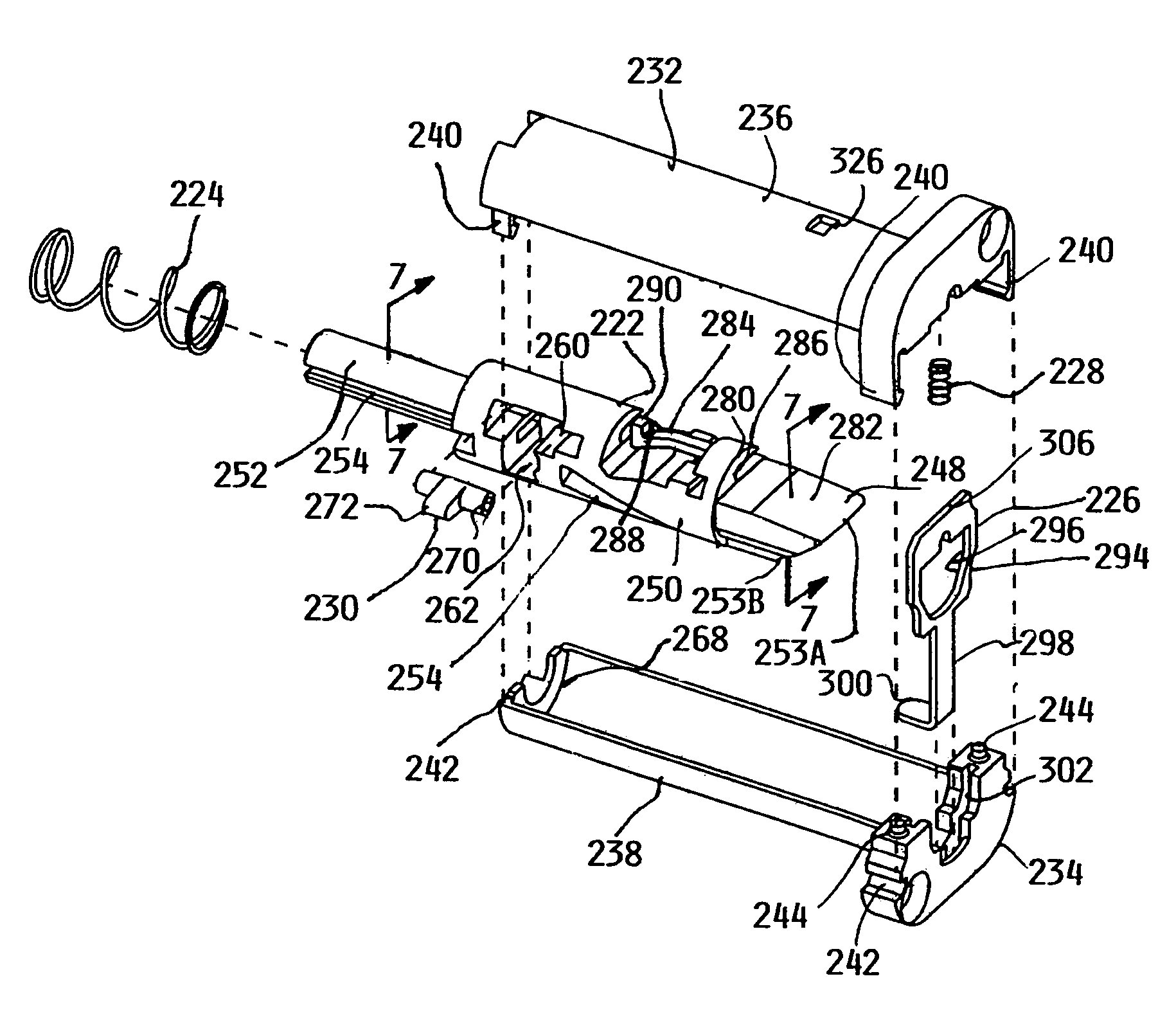
[0064]As depicted in FIG. 4, tilt lock latch assembly 30 generally includes actuator assembly 32, tilt latch assemblies 34, and linking member 36. Actuator assembly 32 generally includes a housing 38 defined by base assembly 40 and housing cover 42. Control lever 44 is coupled with housing cover 42 through aperture 46, which receives shank 48 of lever 44 therethrough. Shank 48 has upper portion 50 which is generally cylindrical in shape and lower portion 52 which defines flats 54, 54A. Full height protuberance 55 extends outwardly from flat 54A, while half height protuberance 55A extends outwardly from flat 54. Retainer 56 is received on upper portion 50 of shank 48 and retains lever 44 on housing cover 42 so that lever 44 is rotatable about axis A-A relative to housing cover 42 as annotated in FIG. 12.

[0065]As depicted in FIGS. 14-17 and 44-46, base assembly 40 generally includes body 58, sweep cam 60, spool 62, detent spring 64, housing retainer 66, and pick plate 68. Underside 70...


PUM


Abstract

A low-cost combination tilt-lock-latch mechanism for a sliding window that combines ease of installation and adjustment with simplicity of use. The mechanism includes at least one tilt-latch mechanism adapted for mounting in the window sash. The tilt-latch mechanism includes a housing and a plunger having a latch bolt portion retractable within the housing. A plunger latch member automatically latches the plunger in a retracted position to enable tilting of the sash. Further, the mechanism may include an actuator mechanism and a flexible linking member. The tilt-latch may include a locking member adjustable from outside the housing of the tilt latch, to lock the flexible linking member to the plunger, thereby operably coupling the actuator mechanism with the tilt-latch.

Description

RELATED APPLICATIONS[0001]This application claims the benefit of U.S. Provisional Application No. 60 / 647,112, entitled WINDOW LOCK SUITABLE FOR DOUBLE AND SINGLE HUNG WINDOWS, filed Jan. 26, 2005, and U.S. Provisional Application No. 60 / 716,455, entitled LOCK AND LATCH SYSTEM FOR VINYL WINDOWS, filed Sep. 13, 2005, hereby fully incorporated herein by reference.FIELD OF THE INVENTION[0002]This invention relates to window locks, and more particularly to window locks for sliding windows.BACKGROUND OF THE INVENTION[0003]Double-hung windows include two window sashes typically mounted for vertical movement along adjacent parallel tracks in a window frame. Traditional double-hung window designs provide poor washability, because it is difficult for a person located inside a structure in which the window is installed to wash the outside of the window pane. To fully wash the outer surface of such windows (which outer surface is the one which is most often in need of cleaning), the person clea...

Claims


Application Information

Patent Timeline
Patent Type & Authority Patents(United States)
IPC IPC(8): E05C1/10
CPCE05B53/003E05B65/087E05C2007/007Y10T292/0834Y10T292/0997
Inventor NOLTE, DOUGLAS A.BEST, KENNETH E.VELZKE, CLARK A.SUBLISKEY, EDWARD J.ROTONDI, ANTHONY J.WOLF, GLEN
Owner TRUTH HARDWARE
Why Eureka
Try Eureka