Model toy aircraft

a toy aircraft and aircraft technology, applied in the field of aircraft design, can solve the problems of hydroplane crash in spectacular accidents, loss of control, aircraft loosening lift and stalling,

Inactive Publication Date: 2008-01-29
BUTLER ERNEST +1
View PDF19 Cites 12 Cited by
  • Summary
  • Abstract
  • Description
  • Claims
  • Application Information

AI Technical Summary

Problems solved by technology

If the speed of the aircraft through the air decreases below a critical velocity, the aircraft will loose lift and stall when the air pressure difference above and below the wings falls below a critical level.
Occasionally, hydroplanes crash in spectacular accidents after lifting completely off the water and losing all control.
Hydroplane racing boats are not designed for controlled flight in air.
These concepts are not designed for operation on land or for flight out-of-ground effect.
Moreover, WIGs cannot fly stationary in a hover.

Method used


Image

  • Model toy aircraft
  • Model toy aircraft
  • Model toy aircraft

Examples


Embodiment Construction

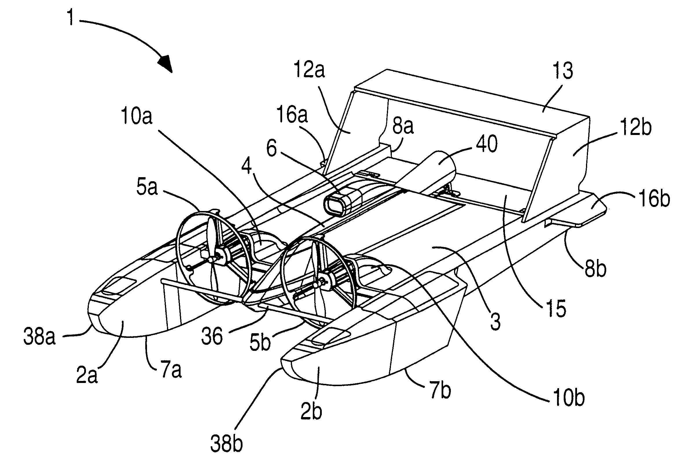
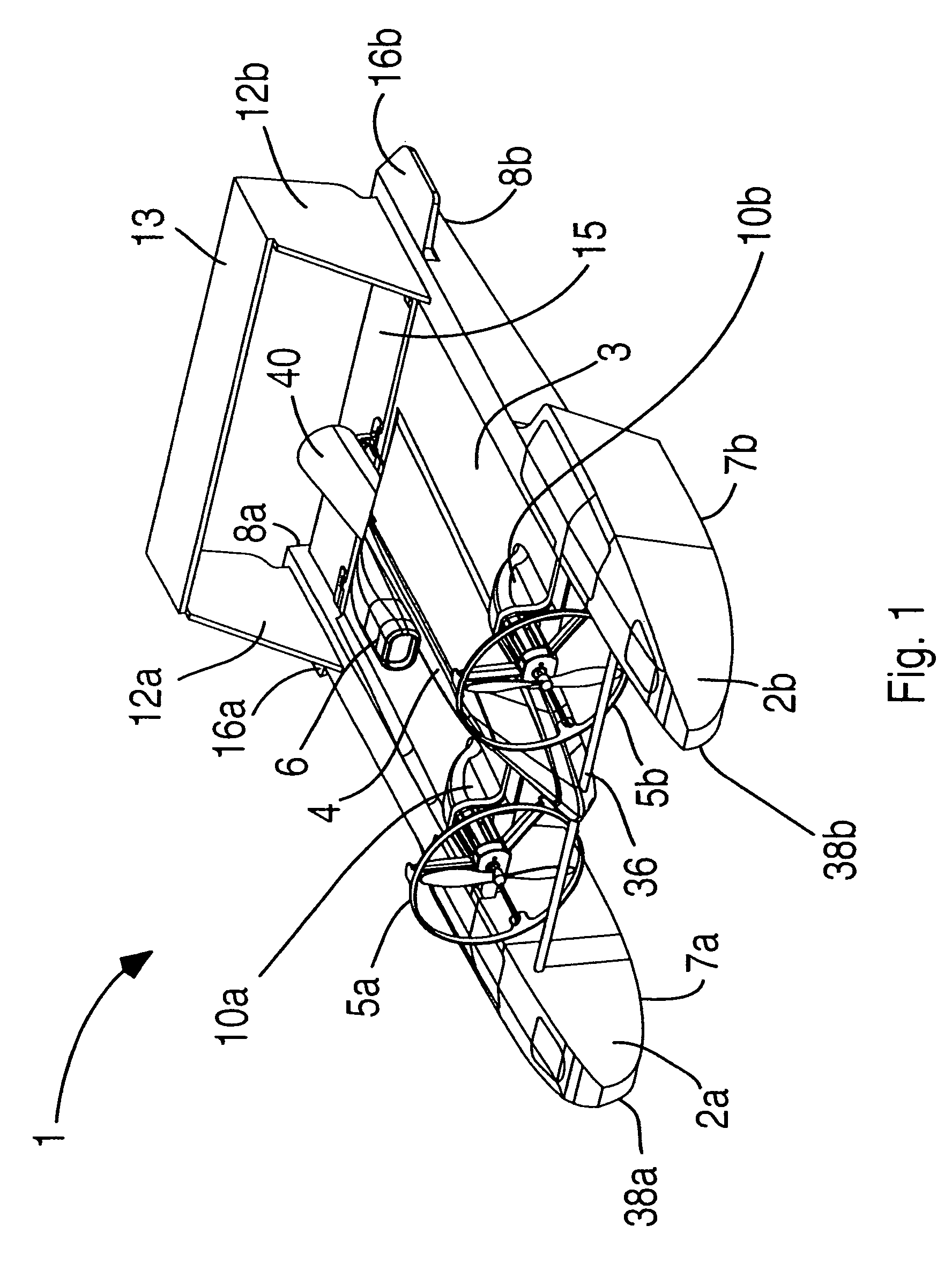
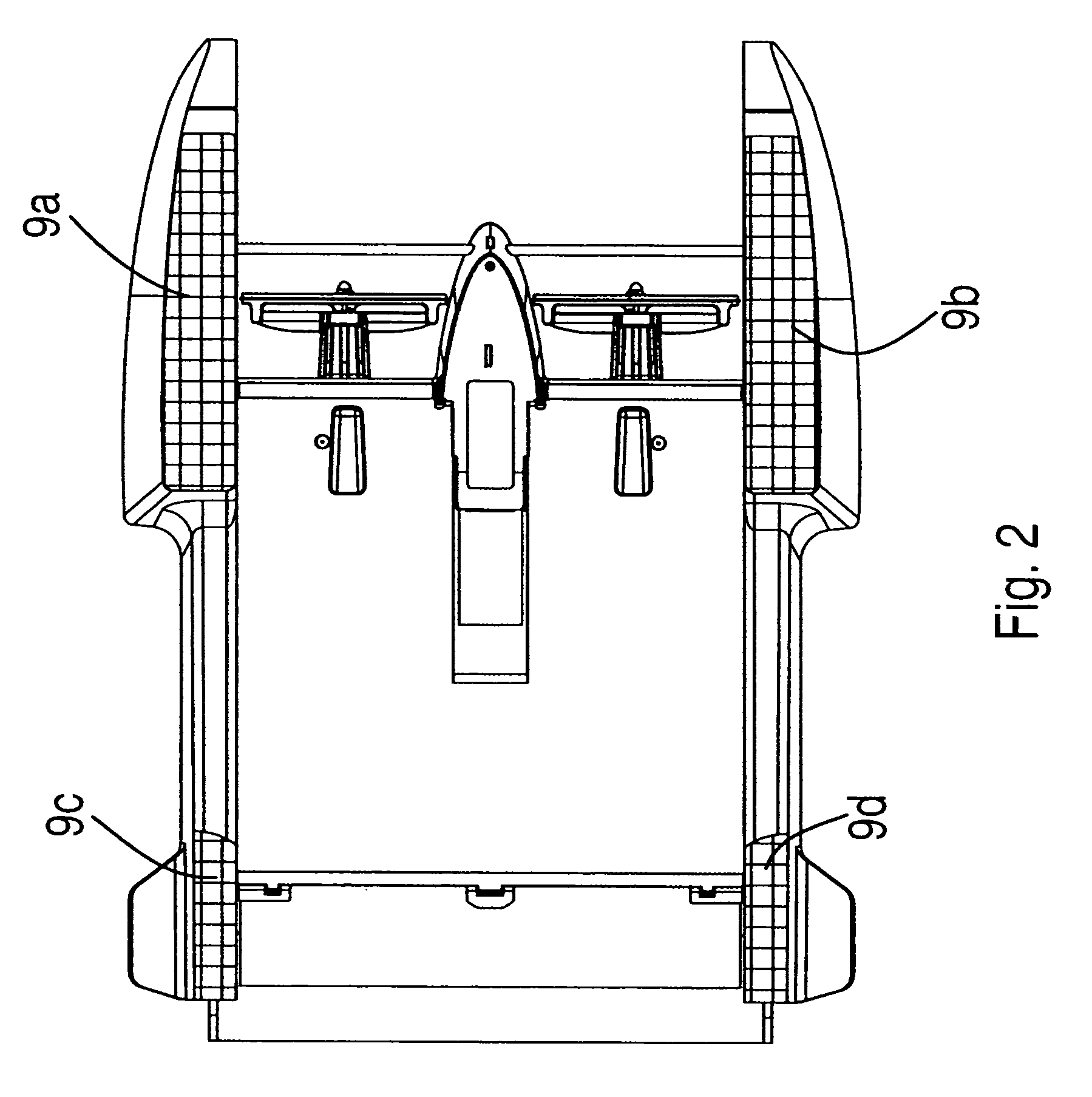
[0032]Referring now to FIGS. 1 to 6, the first embodiment of the model aircraft 1 includes a pair of pontoons 2a and 2b (also known as floats or sponsons) that are separated by a substantially flat central planar wing 3. A fuselage 4, a non-functional air scoop 6 and a non-functional exhaust 40 are mounted on the central section of the planar wing 3, substantially parallel to the pontoons 2a and 2b. As shown in FIG. 12, the fuselage houses system electronics, having a remote control operation system including radio receiver 42, a controller 44, and a power supply 46, an engine (not shown), and a flight surfaces control motor or motors 48.

[0033]One embodiment of the model aircraft 1, as shown in FIGS. 1-6, has two propellers 5a and 5b mounted on the front edge of the central planar wing 3 by means of propeller housings 10a and 10b. The two propellers enable the use of differential thrust to turn the aircraft by driving one propeller faster than the other, rather than using a rudder. ...


PUM


Abstract

A model toy aircraft is adapted for remote control operation on land, on the water and in the air. The toy aircraft includes a pair of pontoons spaced apart by a horizontal wing forming a tunnel hull. A tail section is provided including one or more moveable directional flight control surfaces. A motive mechanism is mounted directly or indirectly to the wing for propelling the aircraft.

Description

RELATED APPLICATIONS[0001]This application claims priority from U.S. Provisional Application Ser. No. 60 / 697,154, filed on Jul. 7, 2005, and is a Continuation-in-part of U.S. patent application Ser. No. 11 / 373,706, which was filed on Mar. 10, 2006. Both applications are hereby incorporated by reference in their entirety.BACKGROUND[0002]1. Field of the Invention[0003]The present invention relates to the field of aeronautics and aircraft design, and provides a novel design particularly suited for model or toy aircraft.[0004]2. Description of the Related Art[0005]Model aircraft have been known for many years, and generally are designed to resemble full sized aircraft. That is, model aircraft have generally consisted of an elongate fuselage, with a central wing extending laterally out from the fuselage, and a tail assembly at the aft end of the fuselage. The tail assembly will generally consist of a vertical tail on which a vertical rudder is mounted, and short horizontal tail wings ext...

Claims


Application Information

Patent Timeline
Patent Type & Authority Patents(United States)
IPC IPC(8): A63H27/00
CPCA63H17/02A63H23/00A63H23/04A63H23/10A63H27/02
Inventor BUTLER, ERNESTCONNALLY, MICHAEL
Owner BUTLER ERNEST
Why Eureka
Try Eureka