
Precisely guided lancet

a precise and lancet technology, applied in the field of precise lancets, can solve the problems of inconvenient and tedious procedures, inability to accurately control the position and difficulty in handling small components for subjects with impaired vision and manual dexterity, etc., to facilitate precise locational control of the puncture site, precise puncture location, and precise positioning of the lancet blade tip

Active Publication Date: 2008-01-29
FACET TECH LLC
View PDF44 Cites 131 Cited by
  • Summary
  • Abstract
  • Description
  • Claims
  • Application Information

AI Technical Summary

Benefits of technology

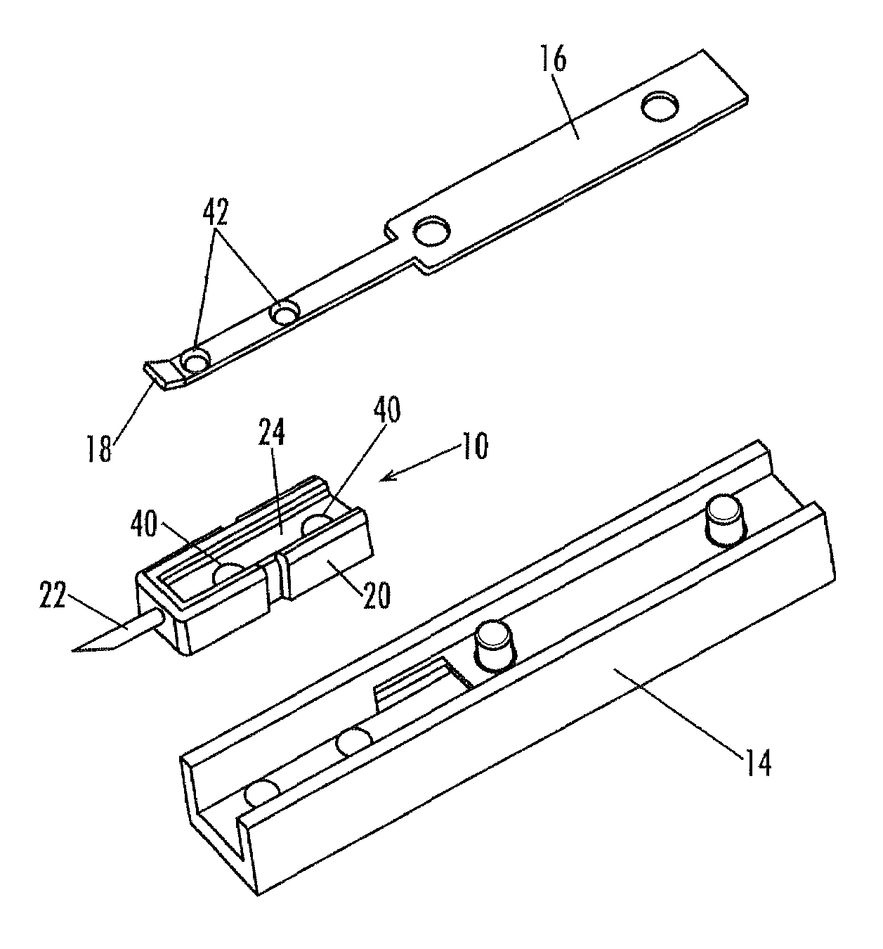
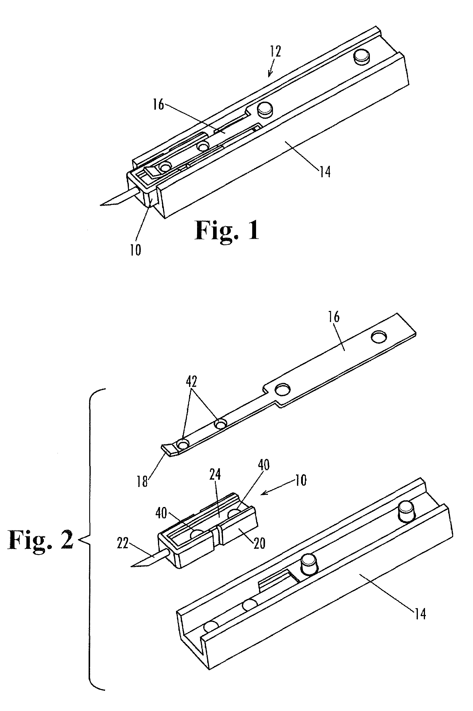
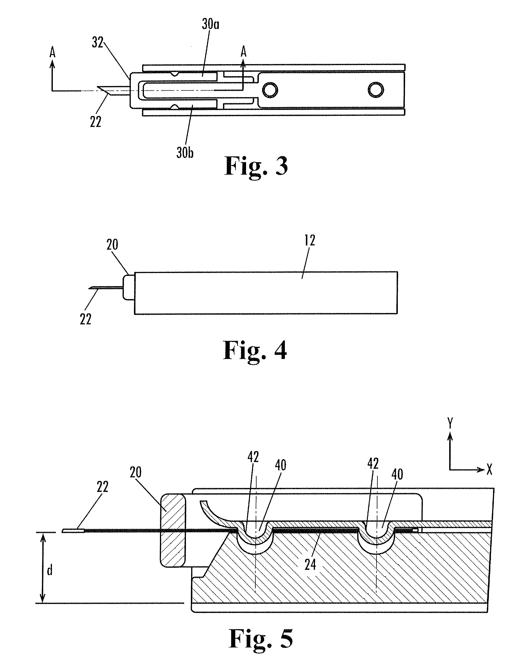
[0008]Briefly described, the present invention facilitates precise locational control of the puncture site by providing a lancet with at least one exposed shank portion of the lancet blade for direct engagement with the lancet carrier of a lancing device, so that variations in the dimensions of the plastic body and in the positioning of the lancet blade in the plastic body do not affect the location of the puncture site. In further embodiments of the invention, at least two exposed shank portions of the lancet blade are provided, spaced a distance apart from one another, for engagement with the lancet carrier, to ensure proper alignment of the lancet blade more precise positioning of the lancet blade tip. By directly relating the position of the lancet blade tip to the lancet holding / driving means, several components of potential tolerance stack-ups are eliminated, resulting in a more precise puncture location.

Problems solved by technology

This procedure tends to be inconvenient and tedious, and the handling of small components may be difficult for subjects with impaired vision and manual dexterity.
However, previously known lancing devices and lancets generally do not permit as precise control over the position of the lancing site as would be desired.
Individually, these dimensional variations may be small and within accepted manufacturing tolerances, but their aggregate effect sometimes results in a substantial misalignment of the lancing site and the location of the collection media delivered by an all-in-one sampling and test device.
However, generating a larger sample size typically requires that a larger wound be created during the lancing step, which adversely results in the infliction of more pain on the subject.
Pain resulting from the lancing procedure often negatively affects patient compliance with a prescribed testing regimen, and is always sought to be minimized.

Method used


Image

  • Precisely guided lancet
  • Precisely guided lancet
  • Precisely guided lancet

Examples


Embodiment Construction

[0023]The present invention may be understood more readily by reference to the following detailed description of the invention taken in connection with the accompanying drawing figures, which form a part of this disclosure. It is to be understood that this invention is not limited to the specific devices, methods, conditions or parameters described and / or shown herein, and that the terminology used herein is for the purpose of describing particular embodiments by way of example only and is not intended to be limiting of the claimed invention. Also, as used in the specification including the appended claims, the singular forms “a,”“an,” and “the” include the plural, and reference to a particular numerical value includes at least that particular value, unless the context clearly dictates otherwise. Ranges may be expressed herein as from “about” or “approximately” one particular value and / or to “about” or “approximately” another particular value. When such a range is expressed, another...


PUM


Abstract

A lancet having one or more portions of the shank of the lancet blade exposed for direct engagement with cooperating portion(s) of the lancet carrier of a lancing device. This direct engagement of the lancet blade with the lancet carrier provides more precise positional control of the location of the lancing site by eliminating the effect that any variation in the position of the lancet blade within the lancet body would otherwise have on the positioning of the lancet tip. Tolerance stack-up is thereby reduced and accuracy is improved, reducing the necessary sample size and minimizing pain resulting from the lancing operation.

Description

CROSS-REFERENCE TO RELATED APPLICATION[0001]This application claims the benefit of U.S. Provisional Patent Application Ser. No. 60 / 384,468, filed May 31, 2002; which application is incorporated herein by reference in its entirety for all purposes.FILED OF THE INVENTION[0002]The present invention relates generally to the field of medical devices, and more particularly to improved devices and methods for lancing the skin or other biological tissue of a human or animal subject to obtain a sample of blood or other body fluid for testing.BACKGROUND OF THE INVENTION[0003]Various lancing devices are known for penetrating the skin of a human or animal subject at a lancing site for obtaining a sample of blood or other body fluids. In general, a typical lancing device includes a housing containing a lancet connected to a spring-driven drive mechanism, and further includes a cocking mechanism for arming or energizing the drive-spring, and a trigger mechanism for releasing the drive mechanism t...

Claims


Application Information

Patent Timeline
IPC IPC(8): A61B17/32A61B5/15
CPCA61B5/1411A61B5/150022A61B5/150442A61B5/150717A61B5/150519A61B5/150618A61B5/15113A61B5/15117A61B5/1513
Inventor TAYLOR, WILLIAM C.LEVAUGHN, RICHARD W.SOLIS, MITCHELLSTOUT, JEFFREY T.
Owner FACET TECH LLC
Learn More