Device and method for measuring components

a technology for measuring components and manipulators, applied in the direction of measuring devices, manipulators, instruments, etc., can solve the problem of low absolute deviation in the positioning of the measurement system carried out with the manipulator, and achieve the effect of small error and simple design

Inactive Publication Date: 2008-01-29
CLAAS FERTIGUNGSTECHN
View PDF9 Cites 16 Cited by
  • Summary
  • Abstract
  • Description
  • Claims
  • Application Information

AI Technical Summary

Benefits of technology

[0009]It is ensured via the decentral arrangement, according to the present invention, of the reference features and the measurement procedure that the absolute distance between the calibration position at which the last calibration of the coordinate system was carried out before a test object was measured, and the measurement position where the test object is actually measured is small. Since the positioning errors of the manipulator are largely relative errors, however, the absolute magnitude of which depends on the length of path covered, this necessarily also results in a very low absolute deviation in the positioning of the measurement system carried out with the manipulator. The present invention therefore enables measurements that are considerably more accurate, thereby also enabling highly precise measurements of large components, with which only minimal tolerances of deviation are permitted.
[0010]A corresponding device for measuring components according to this method must first include a manipulator and a measurement system located on the manipulator such that the measurement system is movable in space using the manipulator. A particularly high flexibility of measurement of components with complex designs is achieved when the manipulator is configured as a multi-axis working robot that can move to the most diverse component positions with great flexibility.
[0014]With a very particularly preferred exemplary embodiment, a group of test objects on the component to be measured is assigned to at least one of the reference features. Depending on the precision required, before the entire group of test objects is measured, for example, the coordinate system of the manipulator can be calibrated once based on the reference feature assigned to this group of test objects, the reference feature being located in the region of the group of test objects. The test objects in this group are then measured. As soon as the measurements have been carried out on all test objects in the particular group, a further group of test objects can be moved to, where the manipulator coordinate system is first recalibrated based on the reference feature located there. In the case of measurements that must be carried out with particularly high precision, the assigned reference feature can be moved to anew before every measurement of a test object in a group of test objects to also calibrate the coordinate system between the measurements of the individual test objects. In general, a plurality of reference features can also be assigned to a test object or a group of test objects, and the measurement accuracy can be improved even further, e.g., via interpolation.
[0016]Furthermore, this component carrier must include a number of reference features located in various defined positions close to the component that has been positioned on the component carrier. This design has the advantage that the reference features need not be repositioned to measure every single component, but rather can remain on the component carrier, and the component, to be measured, is simply positioned in the component carrier accordingly. It is also possible, in principle, to use a plurality of component carriers in a process chain, the component carriers having an identical design and identical reference features in the same positions.
[0021]With an exemplary embodiment having a particularly simple design, when the manipulator is fixed in place, the measurement system for measuring the reference feature and the test objects of the component is positioned on the manipulator such that it is linearly movable along a measurement system axis and / or pivotable around a measurement system axis. By way of the linearly movable or pivotable coupling of the measurement system via an additional measurement system axis, preferably on the outer end of the manipulator, it can be ensured in a very simple manner that a measuring range is scanned by the sensing area of the contour measuring device, to thereby carry out an exact measurement of the entire region and the objects located therein without the manipulator itself having to be moved. In this case, when a calibration is carried out, the exact position (i.e., the spacial coordinates and the orientation) of the measurement system axis is determined, particularly preferably, in a coordinate system that is fixed relative to the reference feature and, therefore, the component and / or the component carrier.
[0022]With regard for the component carrier and / or the component, the reference features represent geometric reference points that are fixed in position, the positions in space of which are preferably stored in a corresponding calculating unit in the measurement system. Since the distances of the measured test objects relative to the assigned reference feature can be determined exactly by data processing systems of simple design, and the distances of the individual reference features on the component carrier are also known exactly, the distances between different test objects on the component can also be determined over larger distances with relatively small error. The error that must be accepted is then essentially only in the magnitude of the relative error of the manipulator position based on the short distances between the test objects and the associated reference features and / or between the particular calibration and measurement positions. The absolute error generated in this manner is extremely small relative to the total distance between the test objects. As a result, the geometry of larger components can also be depicted by measuring the positions of individual test objects located far apart from each other on the component, provided they are in a spacial coordinate system, such that this measurement data can also be used to qualitatively determine the geometry not only of the individual test objects, but also of the entire component. As a result, It is possible to determine deviations of form and position of the individual measured objects on the component and deviations of form of the overall component. To easily perform a complete calibration of the manipulator coordinate system and, in particular, to determine the exact position of the measurement system axis in all of its degrees of freedom in a measurement, it is possible to use geometric bodies, preferably pyramid-shaped geometric bodies, as the reference features. When the reference features are scanned using the optical sensing area of a contour measurement device, the exact position of the measurement system radiating the sensing area can be determined very easily based on the position of the edges and surfaces of a geometric body of this type.

Problems solved by technology

Since the positioning errors of the manipulator are largely relative errors, however, the absolute magnitude of which depends on the length of path covered, this necessarily also results in a very low absolute deviation in the positioning of the measurement system carried out with the manipulator.

Method used


Image

  • Device and method for measuring components
  • Device and method for measuring components
  • Device and method for measuring components

Examples


Embodiment Construction

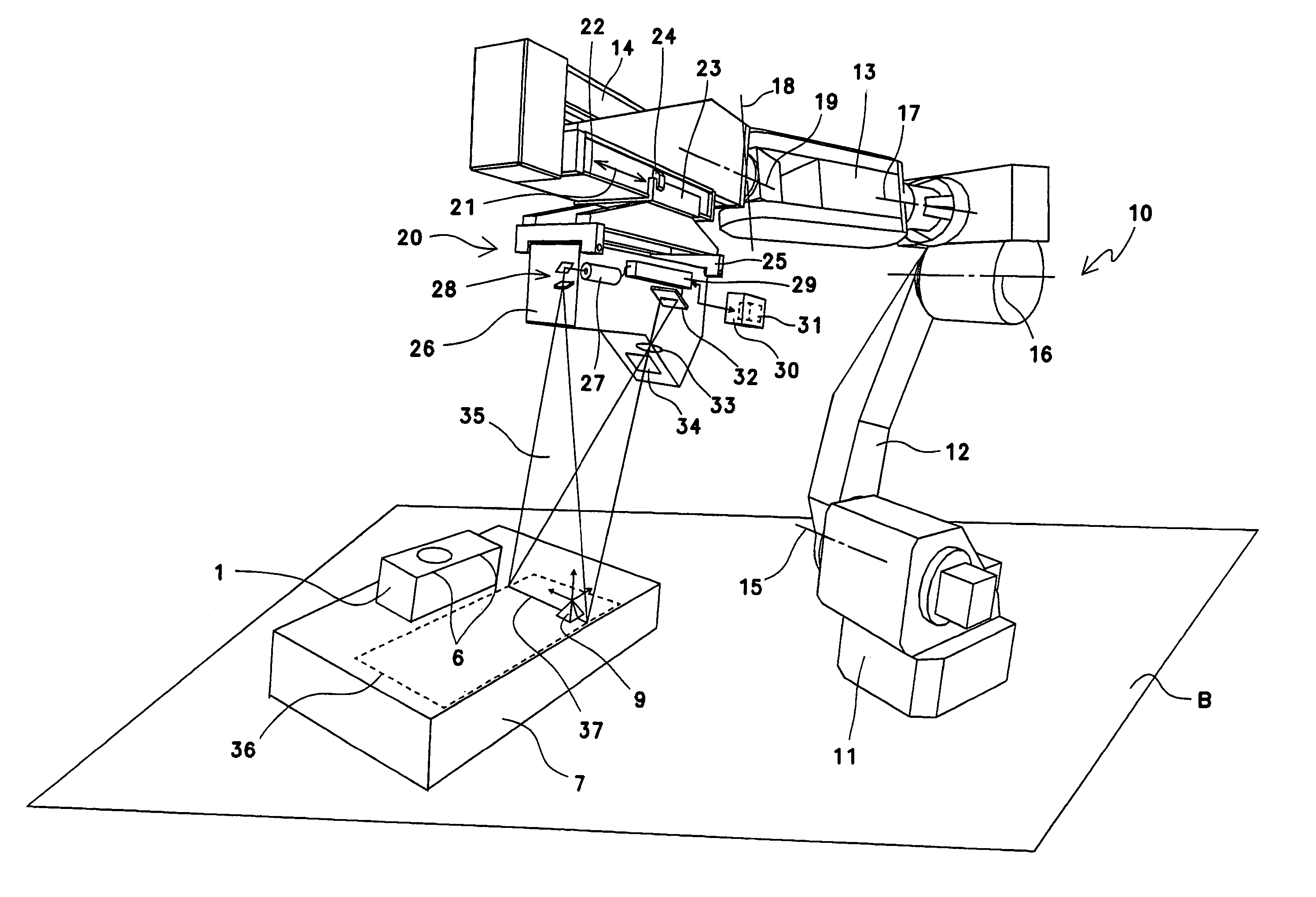
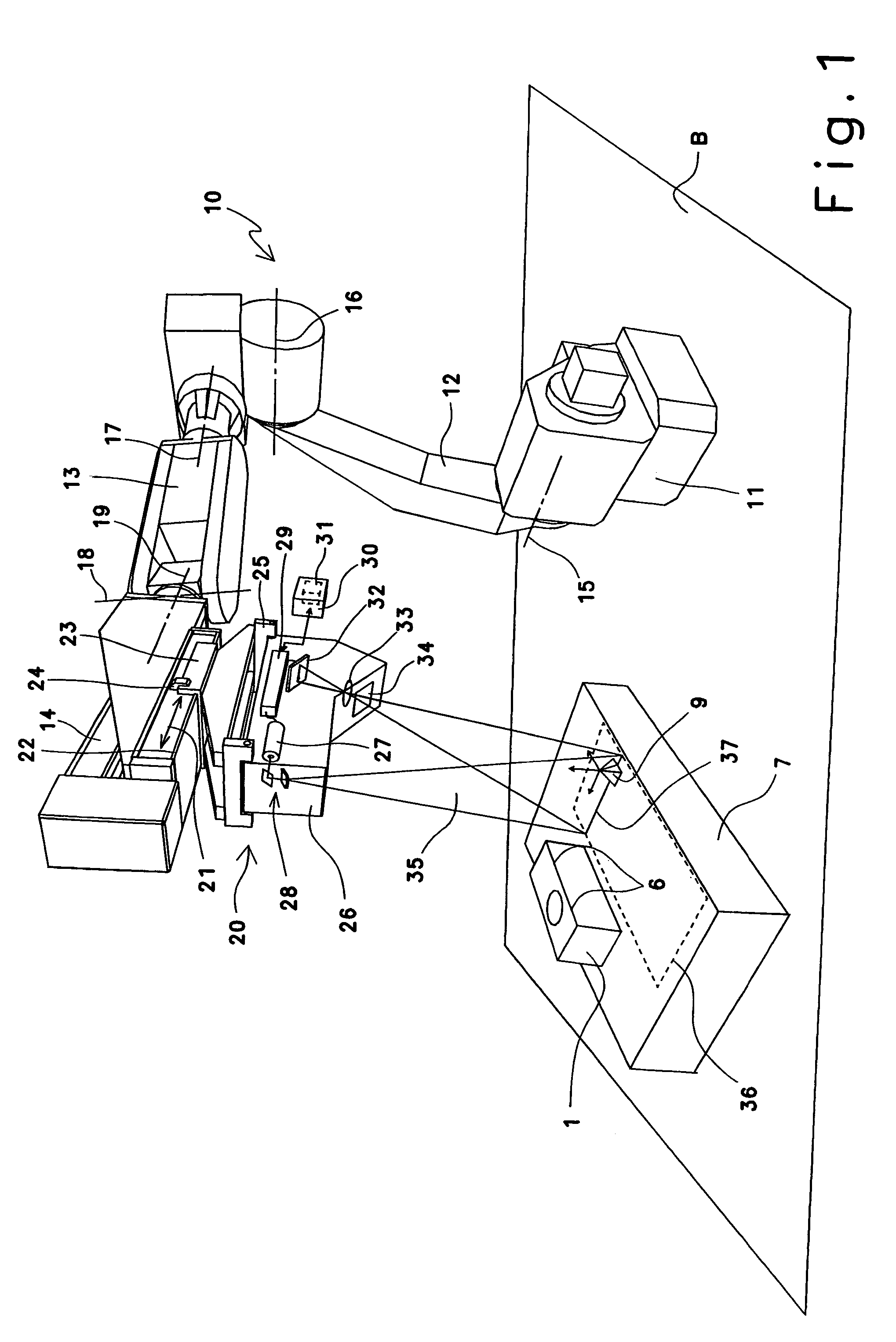
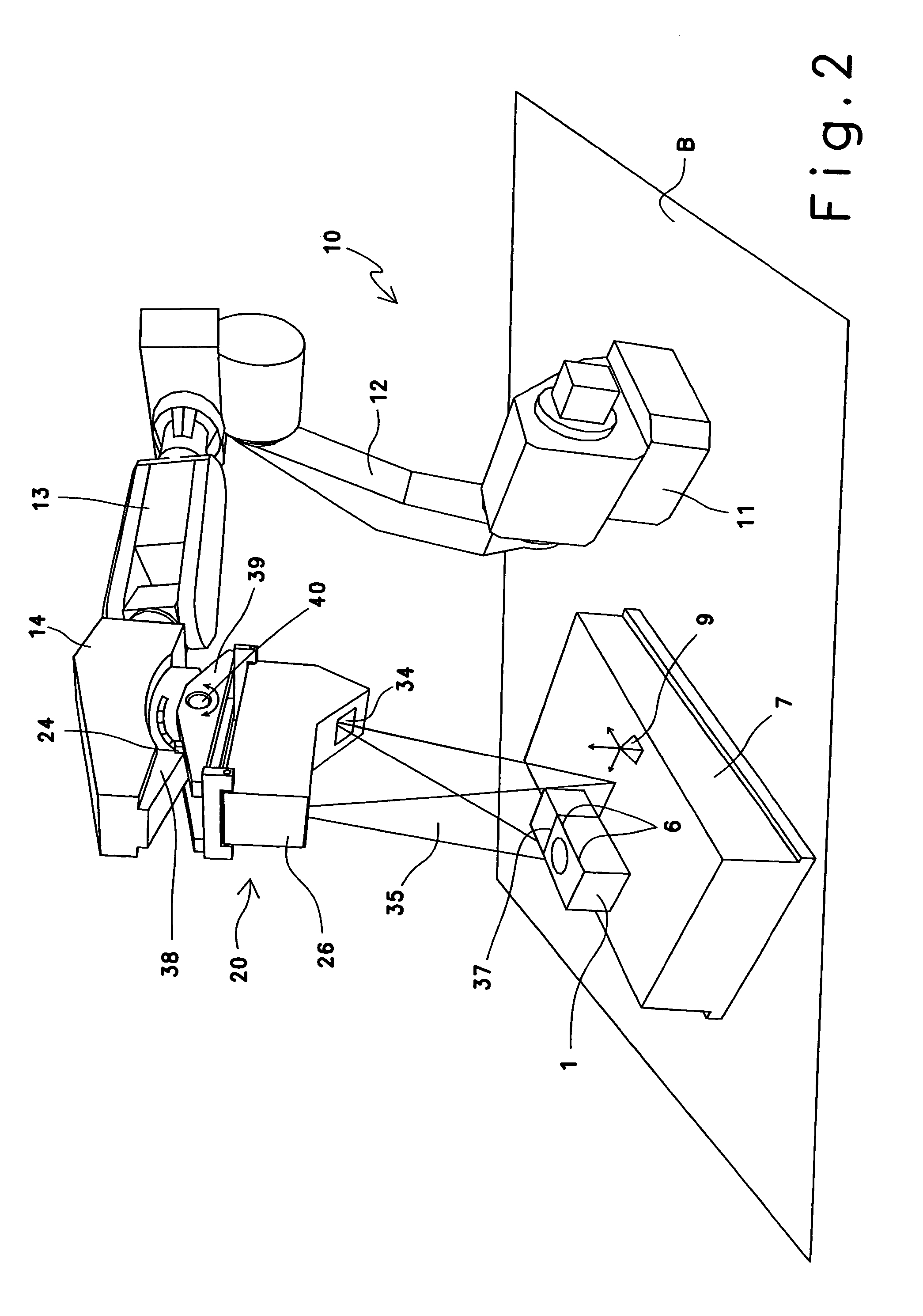
[0027]A manipulator 10 designed as an assembly and production robot 10, referred to below as a working robot 10, is shown in FIG. 1. Working robot 10 is anchored on the bottom side in base B via a pedestal 11 such that it is fixed in position. Working robot 10 includes a plurality of segments 12 through 14 in a manner known per se, which, in totality, form the tool carrier. Individual segments 12 through 14 are movable around a large number of horizontal and vertical swivel axes 15 through 19.

[0028]In the exemplary embodiment shown, outer segment 14 of working robot 10 accommodates a retaining device configured in the manner of a linear guide system with a guide rail 22 and a guide carriage 23. Guide rail 22 is secured to outer segment 14 of working robot 10. An adapter piece 25 that holds measurement system 20 is secured to guide carriage 23. When working robot 10 is fixed in place, measurement system 20 is therefore capable of being moved along a linear measurement system axis 21....


PUM


Abstract

A method is disclosed for measuring components (1) using a measurement system (20) guided by a manipulator (10). In this process, reference features (9, 9a, . . . , 9i) are decentrally located at various positions near a component (1) to be measured, the reference features each being assigned to at least one measuring object (6) located at a close distance to the particular reference feature (9, 9a, . . . , 9i) on the component (1) to be measured. Before a test object (6) is measured, the measuring system (20) is first brought into a calibration position using the manipulator (10), and the reference feature (9, 9a, . . . , 9i) assigned to the particular test object (6) is measured using the measuring system (20) to calibrate a coordinate system of the manipulator (10). Using the manipulator (10), the measuring system (20) is then moved into a measurement position, where the relevant test object (6) is measured. A corresponding device for measuring components and a component carrier (7) are also disclosed.

Description

[0001]CROSS-REFERENCE TO RELATED APPLICATIONS[0002]This application contains some subject matter which has similarities with the subject matter of earlier patent application Ser. Nos. 11 / 385,116 and 10 / 931,598.BACKGROUND OF THE INVENTION[0003]The present invention relates to a method for measuring components using a measurement system guided by a manipulator, preferably by a multi-axis working robot, and a corresponding device for measuring components, with a manipulator and a measurement system located on the manipulator such that the measurement system is movable in space using the manipulator. The present invention also relates to a component carrier for use in a method of this type.[0004]Modern assembly and production processes are based increasingly on the use of assembly and production robots, the position of the actuators of which is changeable with a rotational motion around a large number of swivelling axes to achieve high spacial flexibility of motion of the robot. The pro...

Claims


Application Information

Patent Timeline
Patent Type & Authority Patents(United States)
IPC IPC(8): G01B11/24B25J9/16G01B11/25G01B21/04
CPCG01B11/25G01B21/042G05B2219/37017
Inventor HERRMANN, GUENTERHILBK-KORTENBRUCK, FRANK
Owner CLAAS FERTIGUNGSTECHN
Why Eureka
Try Eureka