Protection device

a protection device and protection device technology, applied in the direction of electronic switching, emergency protection arrangements for limiting excess voltage/current, pulse techniques, etc., can solve problems such as unsuitability for operation

Active Publication Date: 2008-01-29
BOURNS INC
View PDF8 Cites 47 Cited by
  • Summary
  • Abstract
  • Description
  • Claims
  • Application Information

AI Technical Summary

Benefits of technology

[0008]It is an object of the present invention to provide an active protection device which may serve as an alternative to known types of fuses and at least minimises some of the disadvantage referred to above.

Problems solved by technology

Thus, the embodiments of U.S. Pat. No. 5,742,463 were unsuitable for operation with inputs which were level shifted and where transients occurred and the input did not return to zero or near zero after the occurrence of the transient that caused the series connected transistors to assume their cut-off condition.

Method used


Image

  • Protection device
  • Protection device
  • Protection device

Examples


Embodiment Construction

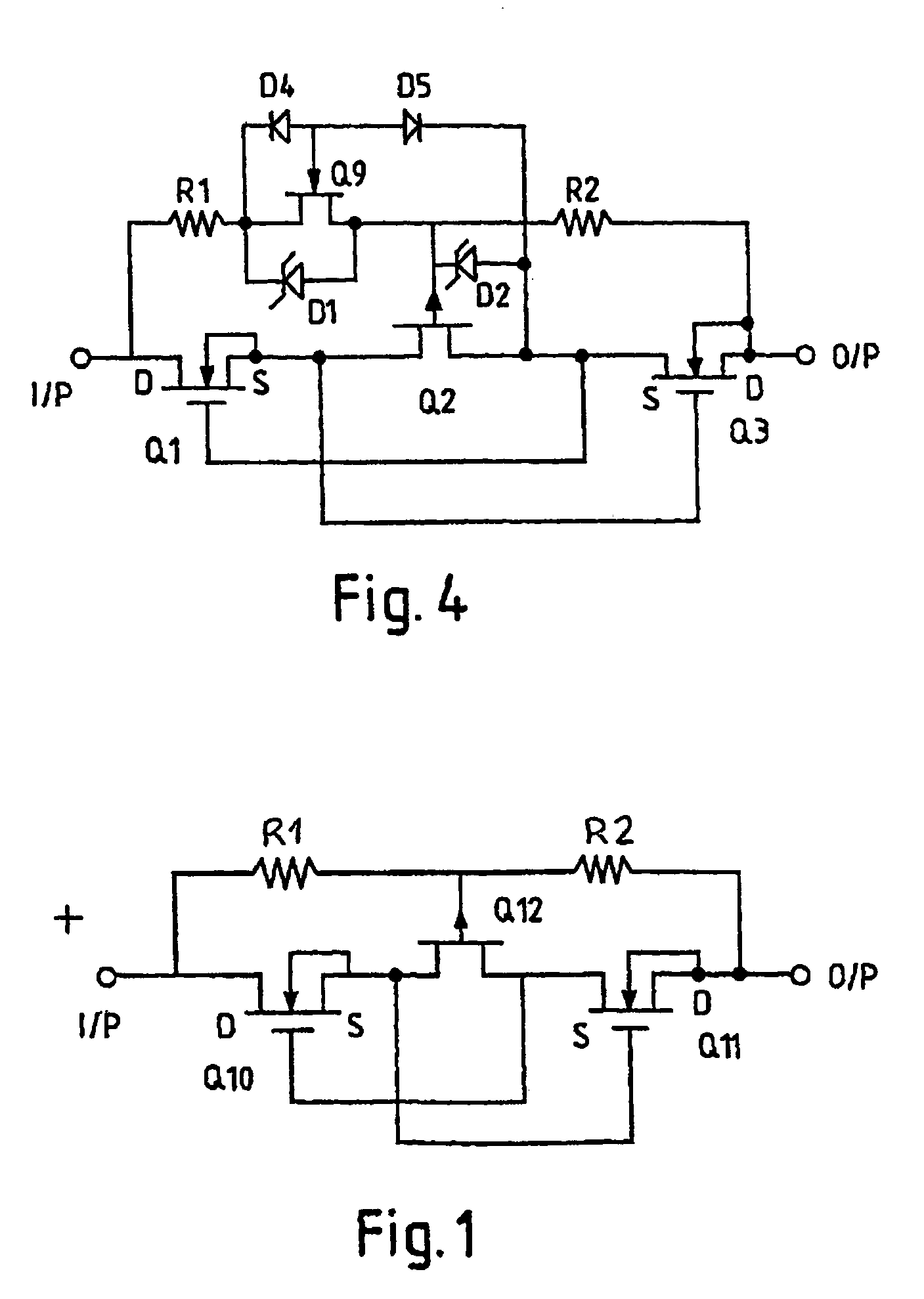
[0018]FIG. 1 shows a TBU circuit suitable for bipolar operation. The depletion mode N channel MOSFETS Q10 and Q11 are in series with depletion mode P channel JFET Q12. With the input more positive than the output and where the input (or through) current is below a threshold current all three transistors Q10 to Q12 are conducting. When a current greater than the threshold current is applied through the TBU, MOSFET Q10 and JFET Q12 cease conducting for positive currents and MOSFET Q11 and JFET Q12 for negative currents and the input is isolated from the output. For the circuit to reset the input must return to zero or near zero. The commutating diodes of U.S. Pat. No. 5,742,463 may be eliminated when Q10 and Q11 are MOSFETs and Q12 is a JFET and a current source, which in its simplest form is a resistor, is used to connect the gate of Q12 to the drain of each of Q10 and Q11. In this figure, transistors Q10, Q12 and Q11 form a variable resistance circuit block and resistors R1 and R2 a...


PUM


Abstract

A protection device is enclosed. The device has a first MOSFET (Q 10), a second MOSFET (Q 11) and a third JFET (Q 12) with their conductive paths in series with the JFET (Q 12) being located between the MOSFETS (Q 10, Q 11). The source of the first MOSFET (Q 10) is connected to the gate of the second MOSFET (Q 11) and the source of the second MOSFET (Q 11) is connected to the gate of the first MOSFET (Q 10). The MOSFETS (Q 10, Q 11) and JFET (Q 12) together form a variable resistance circuit block connectable between an input and an output The gate of the JFET (Q 12) being coupled to the input and the output by respective current sources.

Description

[0001]The present application is a National Stage application of, and claims the benefit of, International Application No. PCT / AU03 / 00175, filed 12 Feb. 2003, and accordingly claims priority to Australian Patent Application Ser. No. PS 0457, filed on 12 Feb. 2002.[0002]This invention relates to a protection device. In particular, the invention concerns a protection device which may function to prevent the flow of undesirable transients or isolate a load from undesirably high voltages or currents.[0003]The device of the invention may be used as an alternative to a fuse. Fuses employing thermal or magnetic elements for effecting control of currents and voltages are known.BACKGROUND ART[0004]U.S. Pat. No. 5,742,463 proposes various active circuits which may function as a protection device and serve as an alternative to known fuses for inhibiting the transmission of transients to a load.[0005]The practical embodiments disclosed in U.S. Pat. No. 5,742,463 employ depletion mode junction f...

Claims


Application Information

Patent Timeline
Patent Type & Authority Patents(United States)
IPC IPC(8): H02H9/00H01L27/04H01L21/822H02H3/08H02H3/087H02H7/00H02H9/02H03K17/08H03K17/30H03K17/687
CPCH02H9/025H03K17/302H02H3/081
Inventor HARRIS, RICHARD ALLEN
Owner BOURNS INC
Why Eureka
Try Eureka