Cooling apparatus for portable computer

Active Publication Date: 2008-02-05
LG ELECTRONICS INC
View PDF27 Cites 66 Cited by
  • Summary
  • Abstract
  • Description
  • Claims
  • Application Information

AI Technical Summary

Benefits of technology

[0014]Accordingly, the present invention is conceived to solve one or more of the aforementioned problems in the related art. An object of the present invention is to provide a cooling apparatus for more smoothly releasing heat generated in a main body of a portable computer to the outside.
[0026]According to the cooling apparatus for a portable computer of the present invention, there is an advantage in that heat generated not only from the microprocessor of the portable computer, but also from several other heat sources on the main board, can be effectively released to the outside.

Problems solved by technology

However, the aforementioned prior art has the following problems:

Method used


Image

  • Cooling apparatus for portable computer
  • Cooling apparatus for portable computer
  • Cooling apparatus for portable computer

Examples


fourth embodiment

[0069]FIGS. 6 to 8 show the configuration of the present invention. As shown in these figures, a predetermined internal space 330′ is defined within a main body 330 of the portable computer. A vent 331 is formed on at least one side of the main body 330. The vent 331 allows the internal space 330′ to communicate with the outside of the main body 330 such that an air stream can be created in the main body 330.

[0070]A main board 332 is installed within the internal space 330′ of the main body 130. Various kinds of component parts of the portable computer are mounted onto the main board 332. First of all, a microprocessor 333 is installed on the main board 332. The microprocessor 333 is a key component of the portable computer and controls the processing works such as command analysis, data operation and data comparison. In operation, the microprocessor 333 produces a great deal of heat.

[0071]Further, a cooling fan unit 335 for releasing heat generated in the main body 330 is provided ...

first embodiment

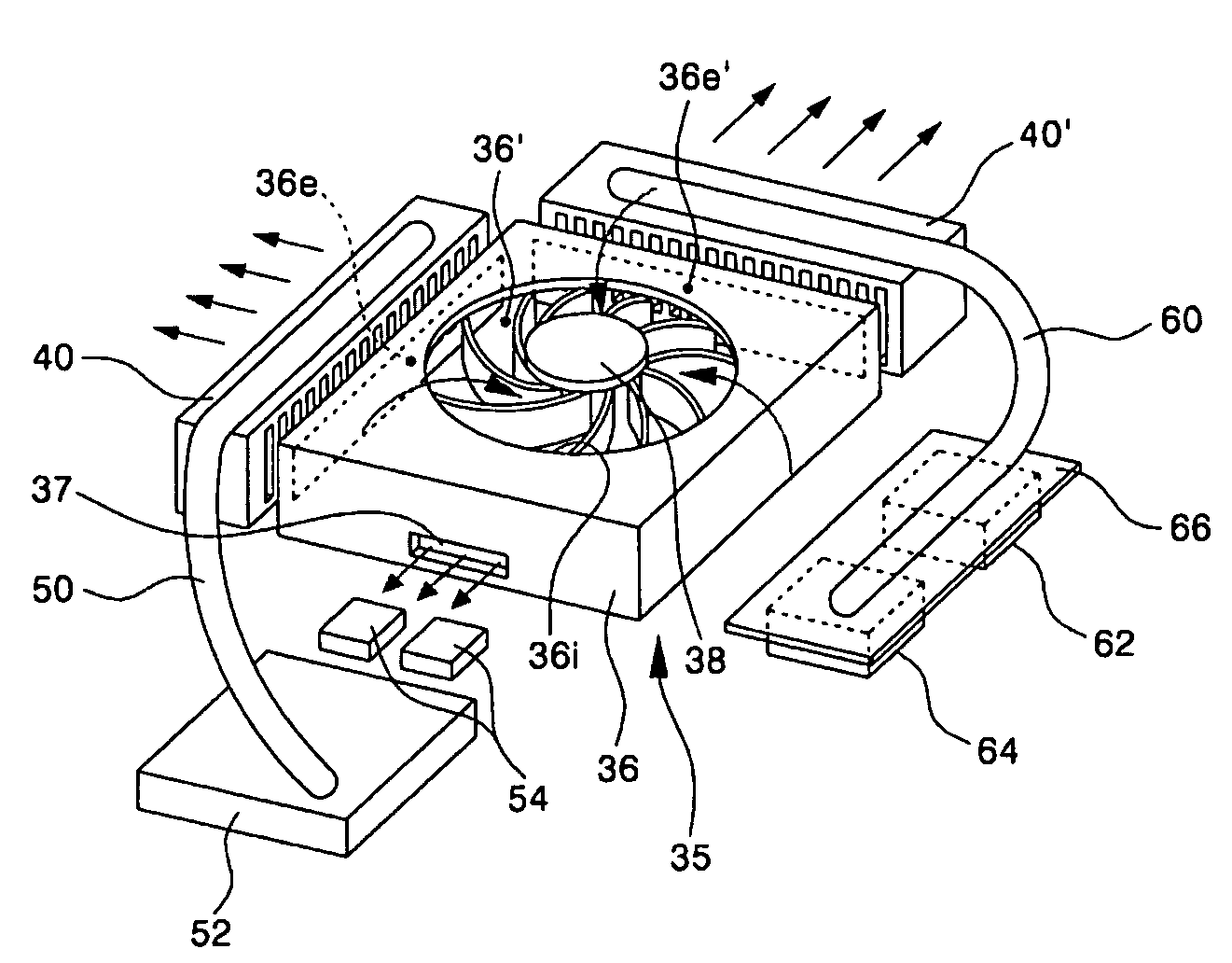
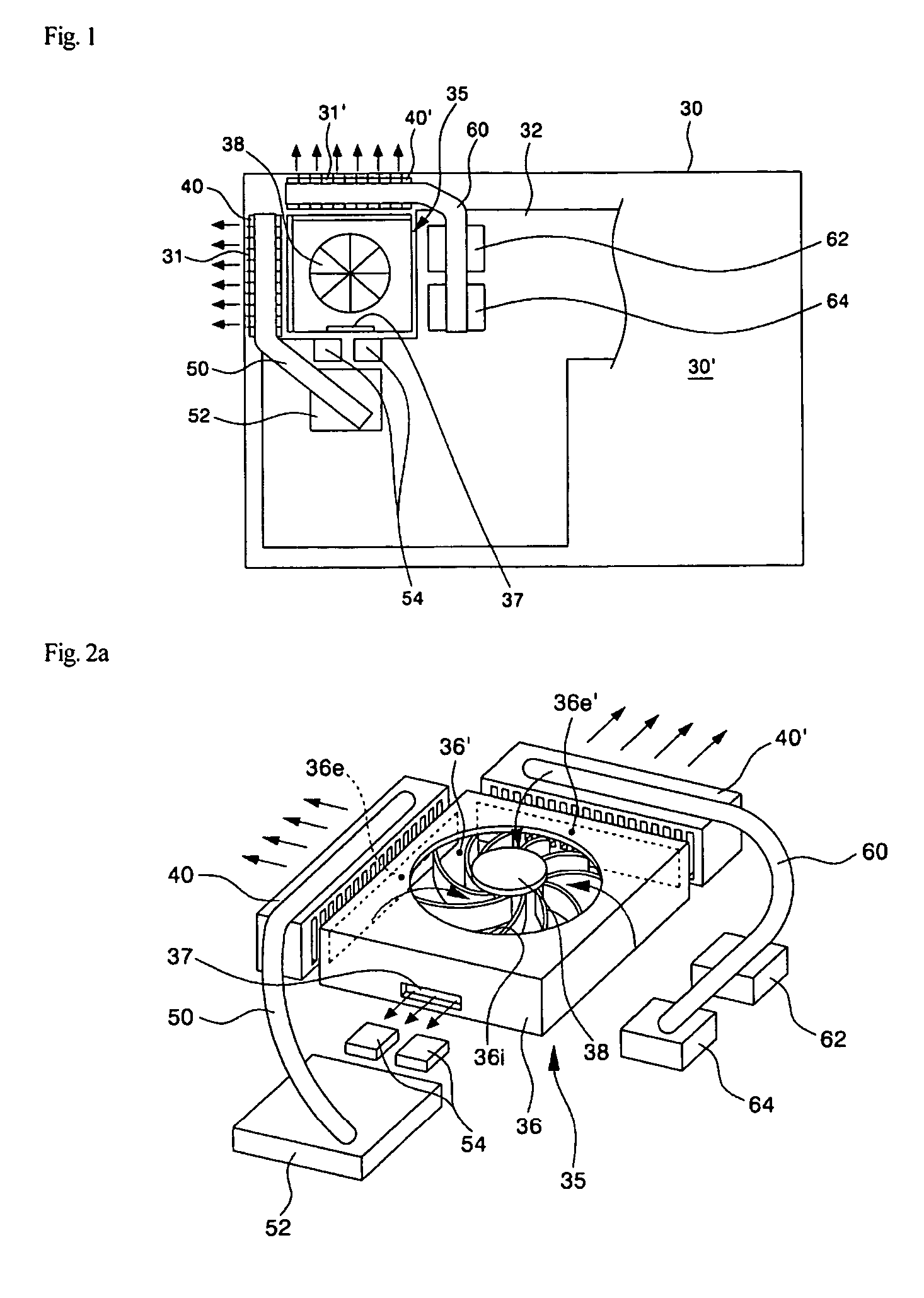
[0080]The cooling operation performed in the cooling structure shown in FIGS. 1 and 2 is first explained. To release heat generated due to the operation of the portable computer, the cooling fan 38 is driven. As the cooling fan 38 is driven, air, in the internal space 30′ of the main body 30, flows into the cooling fan 38 through the inlet 36i.

[0081]The air introduced into the cooling fan 38 is discharged in an outward radial direction from the cooling fan 38 and delivered into the first and second outlets 36e and 36e′. Then, the desired heat exchange is performed between the air delivered into the first outlet 36e and the first cooling fin unit 40 while the air passes through the first cooling fin unit 40. At this time, heat transferred form the microprocessor 52 through the first heat pipe 50 is transferred to the air passing through the first cooling fin unit 40. The heated air is then discharged to the outside of the main body 30 through the vent 31.

[0082]Further, a portion of ...

second embodiment

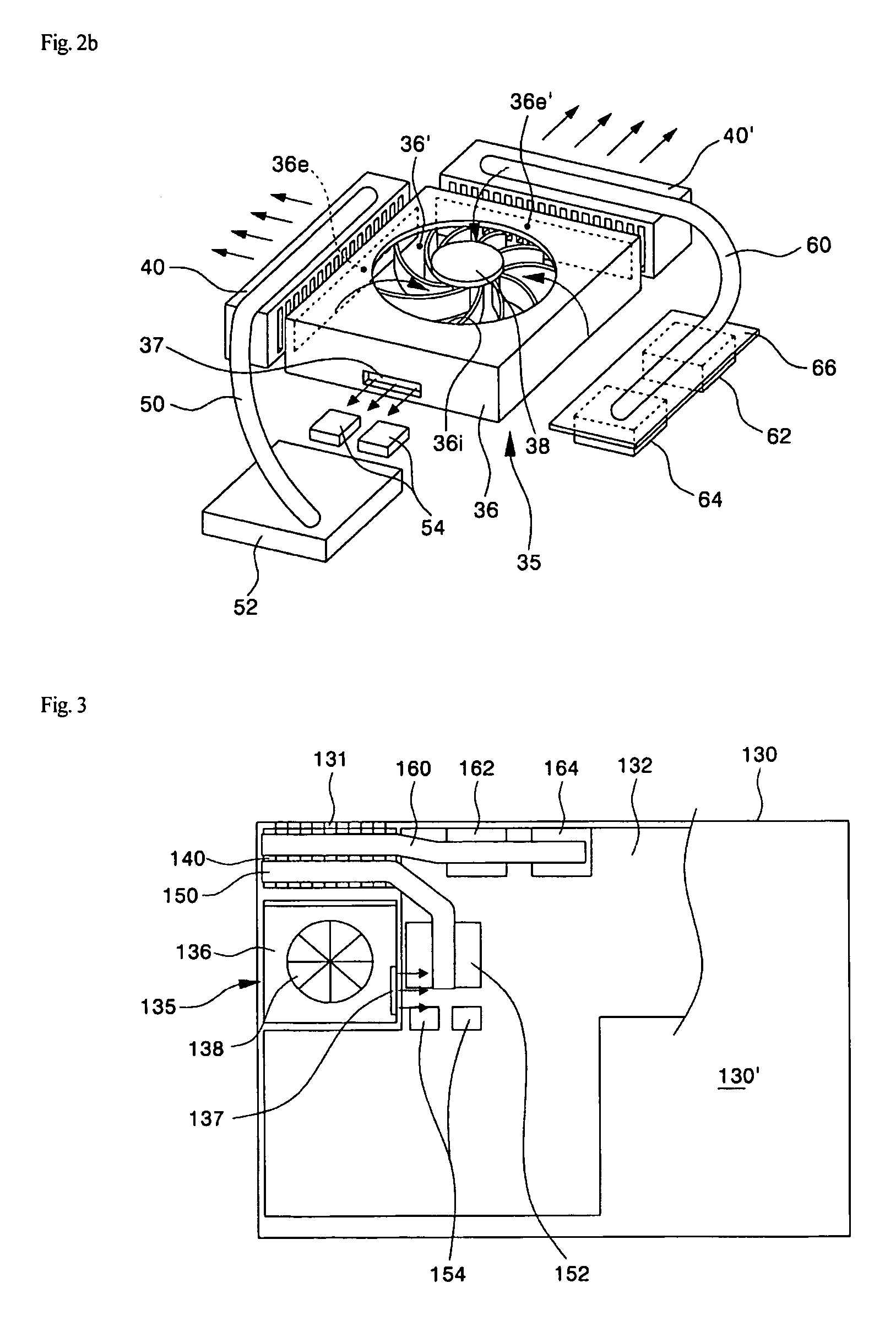
[0084]Next, the cooling operation in the second embodiment is explained with reference to FIGS. 3 and 4. In this embodiment, only a single outlet 136e is formed in the fan housing 136 of the cooling fan unit 135 and the heat transferred through the first and second heat pipes 150 and 160 is transferred to the air passing through the cooling fin unit 140 provided close to the outlet 136e.

[0085]If the cooling fan 138 is driven, air is delivered from the outside of the fan housing 136 to the cooling fan 138 through the inlet 136i. The air delivered into the cooling fan 138 is discharged in an outward radial direction from the cooling fan 138 and delivered into the outlet 136e. Then, the desired heat exchange is performed between the air delivered into the outlet 136e and the cooling fin unit 140 while the air passes through the cooling fin unit 140. At this time, heat transferred from the microprocessor 152 and the chipsets 162 and 164 through the first and second heat pipes 150 and 1...


PUM


Abstract

A cooling structure for a portable computer includes a cooling fan creating an air stream to release heat generated in a main body of the computer to the outside through at least one vent. First and second heat pipes transfer heat generated in first and second heat sources on a main board of the computer to a path of the air stream. A portion of the air stream is also directed to the interior of the main body.

Description

[0001]The present application claims, under 35 U.S.C. § 119, the priority benefit of Korean Patent Application No. P03-080761 filed Nov. 14, 2003, and Korean Patent Application No. P03-085656 filed Nov. 28, 2003. The entire contents of each of these applications are herein fully incorporated by reference.BACKGROUND OF THE INVENTION[0002]1. Field of the Invention[0003]The present invention relates to a portable computer, and more particularly, to a cooling apparatus for use in a portable computer for releasing heat generated in the portable computer to the outside.[0004]2. Description of the Related Art[0005]Portable computers are devices, including notebook computers, tablet computers and the like, which can be used while users carry them. In the present invention, a notebook computer is used as an example of the portable computer.[0006]FIG. 10 shows a perspective view of an external appearance of a general notebook computer. As shown in this figure, the notebook computer 1 is mainl...

Claims


Application Information

Patent Timeline
Patent Type & Authority Patents(United States)
IPC IPC(8): F28D15/00H05K7/20G06F1/20
CPCG06F1/203
Inventor KIM, YE YONGKO, KI TAK
Owner LG ELECTRONICS INC
Why Eureka
Try Eureka