Method for producing nitriding steel

Inactive Publication Date: 2008-02-05
HONDA MOTOR CO LTD
View PDF23 Cites 2 Cited by
  • Summary
  • Abstract
  • Description
  • Claims
  • Application Information

AI Technical Summary

Benefits of technology

[0018]In addition to the passivating of the present invention, higher pitting corrosion resistance can be obtained by

Problems solved by technology

In the case in which extent of oxidizing by heating is insufficient, only a partial passivate

Method used


Image

  • Method for producing nitriding steel
  • Method for producing nitriding steel
  • Method for producing nitriding steel

Examples


Example

[0034]Desirable Examples of the present invention are explained as follows.

(1) Heating Conditions in Passivating Treatment

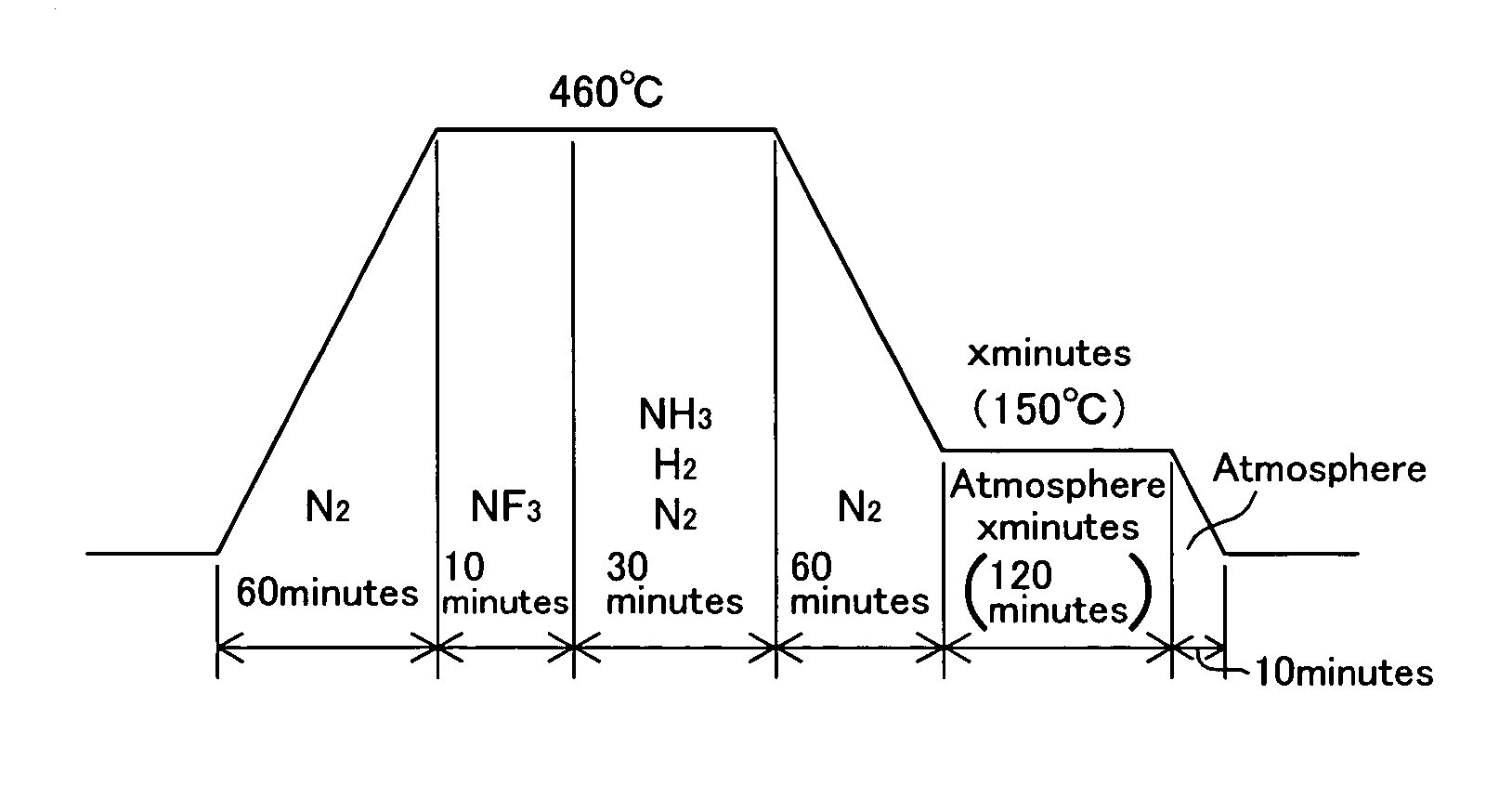
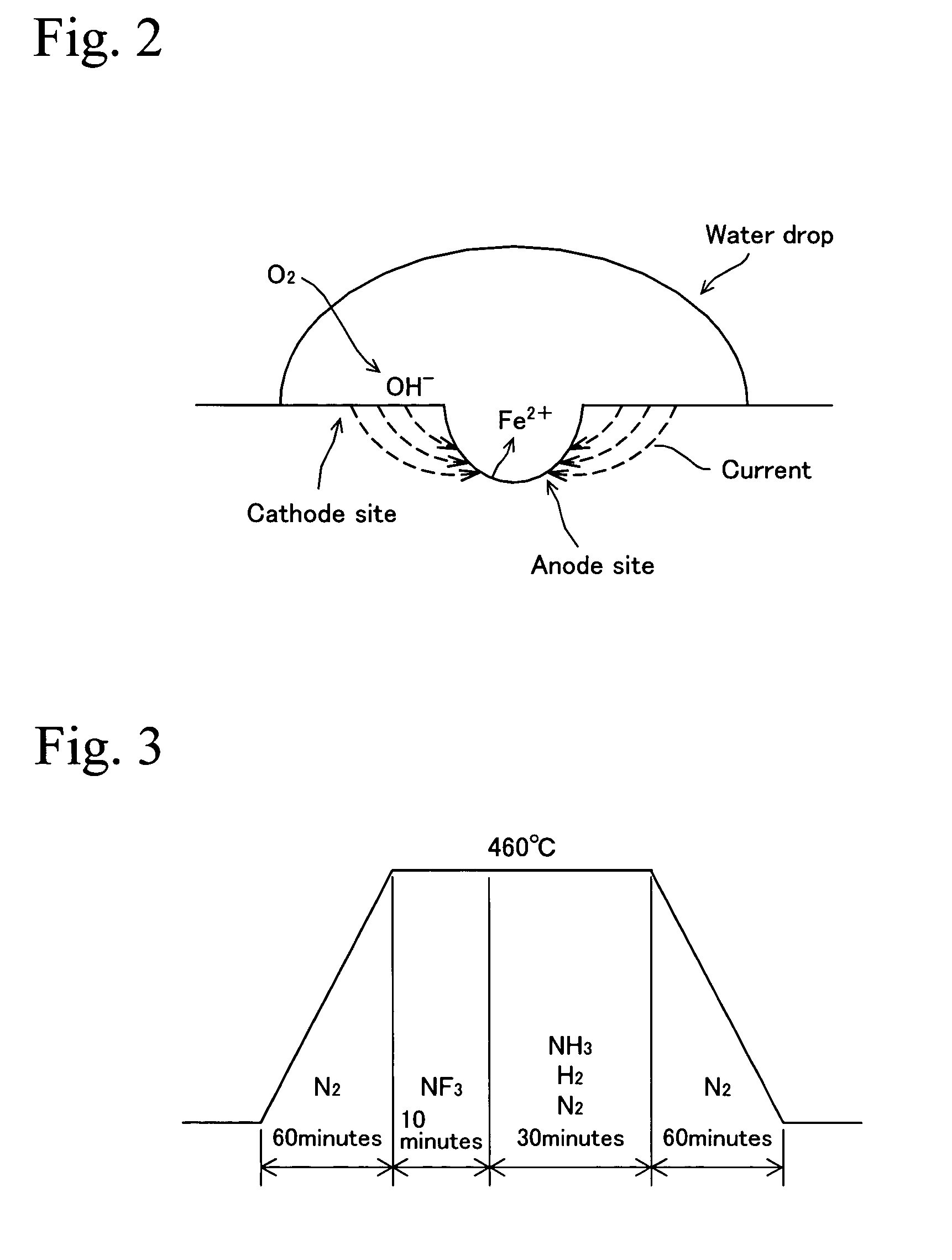
[0035]A number of test pieces were cut from maraging steel having a composition in which elements except Fe and inevitable elements shown in Table 1 are contained. These test pieces were nitrided, and passivating treatment was performed in the air with varying heating condition which is a combination of heating temperature and time to obtain nitrided steel of Examples. The heating condition of FIG. 3 was applied to the nitriding treatment and the heating condition of FIG. 4 was applied to the passivating treatment. Set temperatures and set times are shown in Table 2. On the other hand, the Comparative Examples were obtained in which only the above-mentioned nitriding treatment was performed and the passivating treatment was not performed. The Comparative Examples are shown in a field of treating time 0 min in Table 2. FIG. 8 is a drawing showing a combination of ...


PUM

PropertyMeasurementUnit
Temperatureaaaaaaaaaa

Abstract

In the present invention, after a nitriding process is performed on a steel, a passivating process in which the steel is heated under an atmosphere containing oxygen is performed. The heating condition of the passivating process is within a range surrounded by (100° C., 120 min), (100° C., 10 min), (125° C., 5 min), (190° C., 5 min), (200° C., 10 min), (200° C., 20 min), (190° C., 30 min), (190° C., 40 min), (180° C., 60 min), and (180° C., 120 min) on coordinate axes of temperature and time. In the process for production of the nitrided steel, uniform passivated layer can be easily formed, and fatigue strength is improved as pitting corrosion resistance is improved.

Description

BACKGROUND OF THE INVENTION[0001]1. Technical Field[0002]The present invention relates to a process for production of nitrided steel having high pitting corrosion resistance and superior fatigue strength.[0003]2. Background Art[0004]In recent years, CTV (Continuously Variable Transmission) is widely used as a stepless transmission for automobiles. The CTV is formed by annularly connecting plural pushing blocks with a metallic hoop. High fatigue strength is required for steel used in such hoops and springs because bending force is applied repeatedly. As a technique to improve fatigue strength of various kinds of steel, a nitriding method is known as is disclosed in, for example, Japanese Unexamined Patent Application Publications Nos. 1-142022, 2000-219956, or 2001-26857. However, since the surface is activated during the nitriding process, part of the surface is corroded and pitting corrosion is formed due to the presence of halogens, and corrosion resistance may be deteriorated. Su...

Claims


Application Information

Patent Timeline
IPC IPC(8): C23C8/26C21D1/06C22C38/00C22C38/14C23C8/14C23C8/32C23C8/34
CPCC23C8/32C23C8/34
Inventor ISHII, KAZUOODAGIRI, YOSHIHIROMUNEMURA, TAKESHI
Owner HONDA MOTOR CO LTD
Why Eureka
Try Eureka