Contact image-sensing module having fingerprint scanning function

a technology of contact image and fingerprint scanning, which is applied in the direction of counting objects on conveyors, photoelectric discharge tubes, instruments, etc., can solve the problems of increasing power consumption, affecting product yield, and affecting the product yield, so as to increase the product yield of the whole image-sensing module, increase the fingerprint image processing efficiency, and increase the product yield

Inactive Publication Date: 2008-02-05
DYNA IMAGE CORPORATION
View PDF13 Cites 0 Cited by
  • Summary
  • Abstract
  • Description
  • Claims
  • Application Information

AI Technical Summary

Benefits of technology

[0011]It is an advantage of the present invention that, with the image-sensing module according to the present invention having the fingerprint-scanning function, the light emitted from the light source takes a path with greater room for error when traveling to the sensing element, in order to further increase the product yield of the whole image-sensing module.
[0012]It is another advantage of the present invention that, with the image-sensing module according to the present invention, the light projected upon the fingerprint is more uniform so as to increase the fingerprint image processing efficiency.
[0013]It is another advantage of the present invention that fewer light sources are needed and power consumption is lower than in prior art so as to achieve the purpose of reducing the cost of the whole image-sensing module and extending the lifetime thereof.
[0014]These and other objectives of the present invention will no doubt become obvious to those of ordinary skill in the art after reading the following detailed description of the preferred embodiment that is illustrated in the various figures and drawings.

Problems solved by technology

Additionally, the focusing device 74 has to be appropriately positioned somewhere so as to have the light travel to the linear sensing element array 72, leaving less room for positioning error and demanding higher assembly accuracy, both of which seriously and negatively affect the product yield.
However, the light intensity of these light sources 73 projecting upon the light penetrating device 75 is not uniform, leading to a more complicated fingerprint image processing and thus undermining the processing efficiency.
Furthermore, because of the use of a large number of light sources, the power consumption increases and shortens the lifetime of the whole image-sensing module.

Method used


Image

  • Contact image-sensing module having fingerprint scanning function
  • Contact image-sensing module having fingerprint scanning function
  • Contact image-sensing module having fingerprint scanning function

Examples


Embodiment Construction

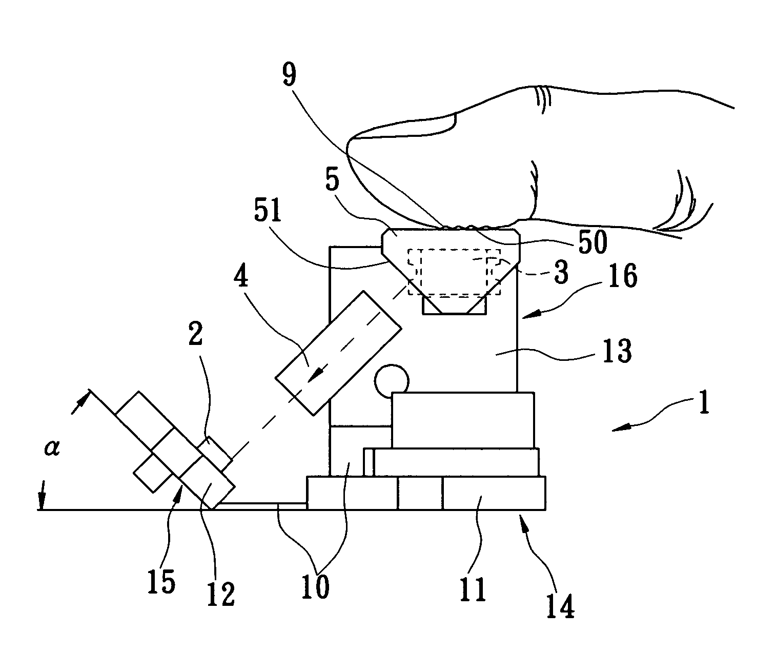
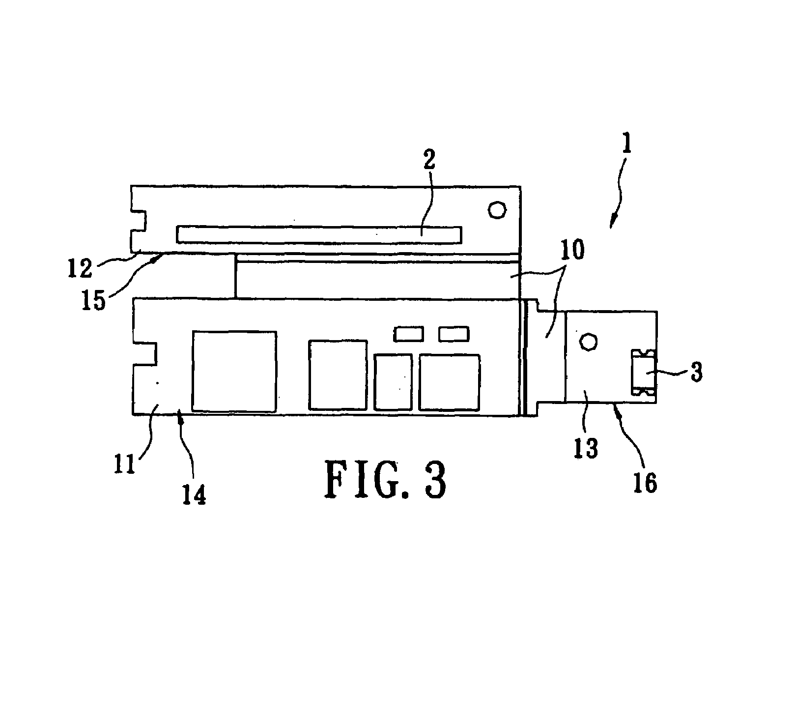
[0031]Reference is made to FIGS. 3 to 10 of schematic diagrams and top views showing the first embodiment according to the present invention. The first embodiment includes a flex / rigid composite substrate 1, a linear sensing element array 2, a light source 3, a focusing device 4, and a light-guiding device 5. The flex / rigid composite substrate 1 includes a first rigid circuit substrate 11, a second rigid circuit substrate 12, a third rigid circuit substrate 13, and at least one flex circuit board 10. Each of first rigid circuit substrate 11, the second rigid circuit substrate 12, and the third rigid circuit substrate 13 electrically connects to at least one flex circuit board 10 and stacks with the associated flex circuit board 10 in order to form a first composite substrate 14, a second composite substrate 15, and a third composite substrate 16. The flex circuit board 10 connected to the first composite substrate 14 and the second composite substrate 15 can be either the same flex ...


PUM


Abstract

A contact image-sensing module having fingerprint-scanning function is described. The image-sensing module has a flex / rigid composite substrate having a first rigid circuit substrate, a second rigid circuit substrate, a third rigid circuit substrate, and at least one flex circuit board. The first rigid circuit substrate, the second rigid circuit substrate, and the third rigid circuit substrate respectively and electrically connect to the flex circuit board in order to form a first composite substrate, a second composite substrate, and a third composite substrate. Each of the second composite substrate and the third composite substrate respectively is not located in the same plane and has a predetermined angle with respect to the plane where the first composite plane is located.

Description

BACKGROUND OF THE INVENTION[0001]1. Field of the Invention[0002]The present invention relates to a contact image-sensing module, and more particularly, to a contact image-sensing module having a fingerprint-scanning function.[0003]2. Description of the Prior Art[0004]An individual's fingerprint is unique, and thus has gradually become one viable option with higher security protection when serving as the individual's password. Along with the popularity of electronic devices and the increase in storage volume thereof, protection of the personal information stored therein against unauthorized invasion becomes more and more important. As the result, having the individual's fingerprint serve as the password for use of electronic devices is becoming a more effective way of protecting personal information from unauthorized use.[0005]Reference is made to FIG. 1, which shows a schematic, cross-sectional view of a prior art image-sensing module with fingerprint scanning function. The image-se...

Claims


Application Information

Patent Timeline
Patent Type & Authority Patents(United States)
IPC IPC(8): H01L27/00G06K9/00G06V40/13
CPCG06K9/00013H05K1/189H05K3/4691H05K2201/047G06V40/13
Inventor CHENG, CHIA-CHULIU, TZU-HENGWANG, MING-HO
Owner DYNA IMAGE CORPORATION
Why Eureka
Try Eureka